A joint replacement registration device and method

A joint replacement and registration technology, which is applied in medical science, surgery, computer-aided planning/modeling, etc., can solve the problems of inability to complete the registration process independently, low operation efficiency, and long operation time, so as to avoid optical positioning displacement Error, reduced operation time, less wear effect

Active Publication Date: 2022-07-12
LANCET ROBOTICS CO LTD
View PDF5 Cites 0 Cited by
  • Summary
  • Abstract
  • Description
  • Claims
  • Application Information

AI Technical Summary

Problems solved by technology

[0003] The purpose of the present invention is to solve the problems of hand-eye incoordination, low operation efficiency and long operation time caused by the inability to complete the registration process independently in the existing operation registration process and the need for an assistant to assist in the operation, and provides a joint replacement registration device and methods

Method used


Image

  • A joint replacement registration device and method
  • A joint replacement registration device and method
  • A joint replacement registration device and method

Examples


Embodiment 1

[0026] A joint replacement registration device, which cooperates with a binocular vision system and a three-dimensional acetabular fossa model software on a computer, is used for image registration between a patient's acetabular fossa and the three-dimensional model of the acetabular fossa. The binocular recognition system is used to identify the position of the registration device, and the three-dimensional model of the acetabular fossa is presented on the computer monitor, and the three cooperate with each other to realize the registration process of the joint replacement.

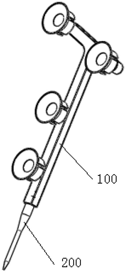
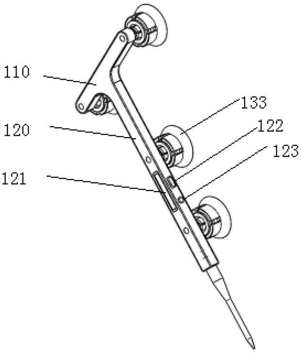
[0027] like figure 1 As shown, the registration device includes a handle 100 and a needle portion 200 , and the needle portion 200 is disposed at the lower end of the handle 100 . The handle 100 is T-shaped and includes a first connecting portion 110 and a second connecting portion 120. The second connecting portion 120 is fixedly connected to the middle of the first connecting portion 110. Considering t...

Embodiment 2

[0044] A method of joint replacement registration

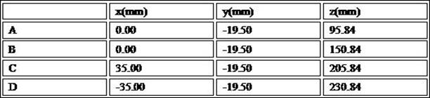
[0045] S100. Acquire the first bony marker point of the patient's acetabular fossa through the registration device, and when the position of the bony first marker point and the position of the three-dimensional model of the acetabular fossa meet expectations, use the first button 122 confirming, performing a registration between the first bony landmark point and the three-dimensional model of the acetabular fossa;

[0046] S200. Use the registration device to click on different planes of the patient's acetabular fossa, and use the second button to drive the rotation of the three-dimensional model of the acetabular fossa until the plane where the point to be registered is located is in the three-dimensional acetabular fossa. The front of the model, then select N second bony landmark points in turn, and confirm through the first button 122, and perform secondary registration between the bony second landmark point and the three-...


PUM


Abstract

The invention relates to a joint replacement registration device, which cooperates with a binocular vision system and acetabular fossa three-dimensional model software on a computer to perform image registration between a patient's acetabular fossa and the three-dimensional model of the acetabular fossa, The registration device includes a handle and a needle, and the needle is arranged at the lower end of the handle; a first button and a second button are arranged on the handle, and the first button is used to confirm the position of the needle, The second button is used to remotely control the rotation of the three-dimensional model of the acetabular fossa; the handle is provided with a signal function module, the first button and the second button are both electrically connected to the signal function module, The signal function module exchanges information with the acetabular fossa three-dimensional model software on the computer; a number of optical tracking marks are distributed on the upper surface of the handle, and the optical tracking marks cooperate with the binocular vision system to determine the The position of the needle and the angle of rotation of the 3D model of the acetabular fossa.

Description

technical field [0001] The invention relates to the field of image registration, in particular to a joint replacement registration device and method. Background technique [0002] The purpose of image registration is to match the virtual 3D model of the lesion with the planned surgical path to the actual human body during surgery. The key step is that according to the prompt of the 3D model of the navigation software, the doctor sequentially collects the virtual markers on the model through the probe in the patient's body, and uses the principle of optical tracking to obtain its position signal. The steps of using traditional probes to collect anatomical markers are cumbersome: after a doctor selects a marker with the probe, another doctor needs to click the confirmation button on the navigation monitor with the mouse, and only after the accuracy meets the system requirements can it be used. Proceed to the acquisition of the next marker point. Some probe technical solution...

Claims


Application Information

Patent Timeline
Patent Type & Authority Patents(China)
IPC IPC(8): A61B34/10A61B34/20
CPCA61B34/10A61B34/20A61B2034/105A61B2034/107A61B2034/108A61B2034/2055
Inventor 黄志俊柏健刘金勇吴雨
Owner LANCET ROBOTICS CO LTD
Why Eureka
Try Eureka