
Convenient-to-use dressing change bed for orthopedics department

An orthopaedic and bed board technology, applied in the field of dressing beds, can solve the problems that the height and angle of the bed board cannot be adjusted, and the injured patients are difficult to lie down and get up, and achieve the effect of facilitating dressing changes.

Active Publication Date: 2021-03-09
WEST CHINA HOSPITAL SICHUAN UNIV
View PDF12 Cites 0 Cited by
  • Summary
  • Abstract
  • Description
  • Claims
  • Application Information

AI Technical Summary

Problems solved by technology

[0005] In order to overcome the disadvantages that the existing orthopedic bed cannot adjust the height and angle of the bed board, and it is difficult for the injured patient to lie down and get up, the technical problem to be solved by the invention is to provide a device that can adjust the height and angle, An easy-to-use dressing changing bed for orthopedics that enables injured patients to lie down and get up

Method used


Image

  • Convenient-to-use dressing change bed for orthopedics department
  • Convenient-to-use dressing change bed for orthopedics department
  • Convenient-to-use dressing change bed for orthopedics department

Examples


Embodiment 1

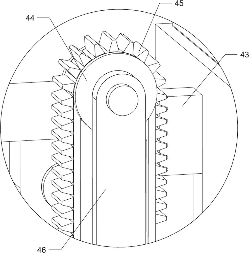
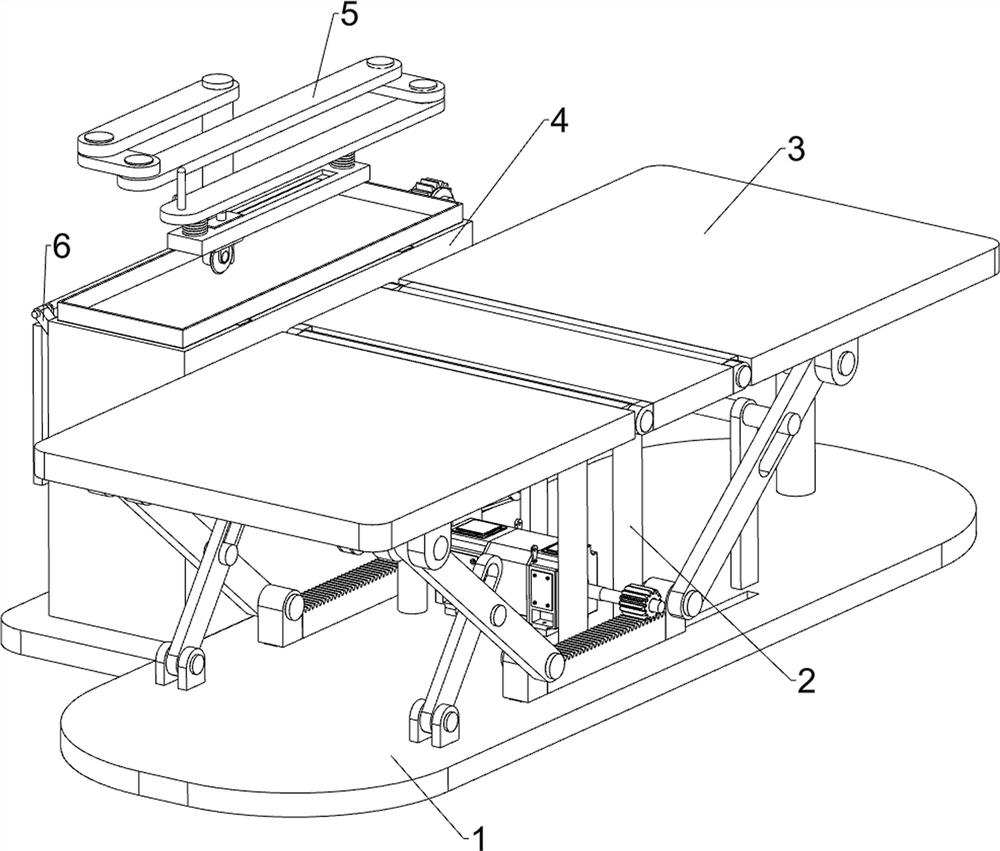
[0023] An easy-to-use dressing changing bed for orthopedics, such as Figure 1 to Figure 4 As shown, it includes a base 1, a support frame 2, a movable bed board mechanism 3 and a lifting box mechanism 4, four support frames 2 are connected in the middle of the top of the base 1, a movable bed board mechanism 3 is arranged between the base 1 and the support frame 2, and the base 1 is provided with a lifting box mechanism 4, and the lifting box mechanism 4 is connected with the movable bed board mechanism 3 through transmission.

[0024] Movable bed plate mechanism 3 includes first movable plate 31, second movable plate 32, fixed plate 33, first slotted connecting rod 34, fixed rod frame 35, connecting rod 36, second slotted connecting rod 37, sliding rack 38. The transmission gear 39 and the servo motor 310, the tops of the four support frames 2 are connected with a fixed plate 33, the right side of the fixed plate 33 is rotatably connected with the first movable plate 31, and...

Embodiment 2

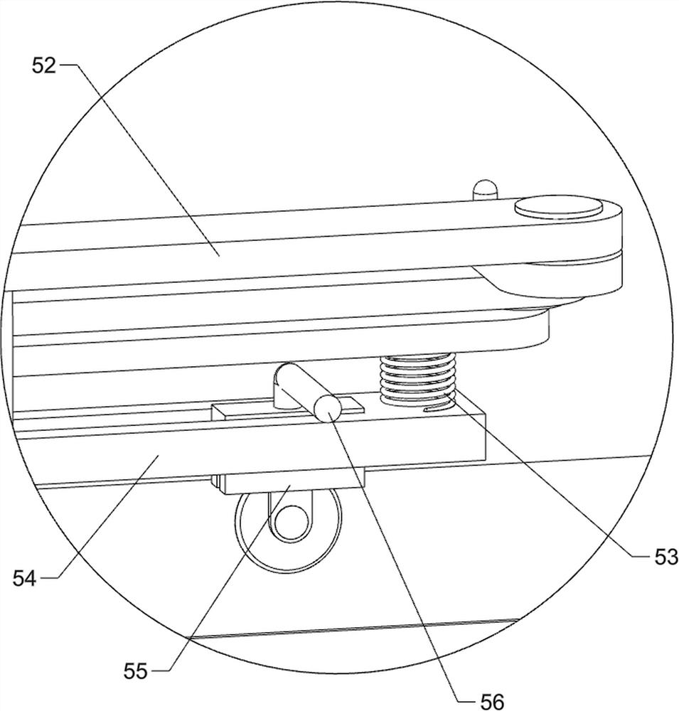
[0028] On the basis of Example 1, such as figure 2 , image 3 and Figure 5 As shown, a cutting mechanism 5 is also included, and the cutting mechanism 5 includes a support column 51, a movable rocker arm group 52, a tension spring 53, a slide rail frame 54, a sliding cutter 55, a first operating rod 56 and a second operating rod 57, the rear side of the top of the lifting platform 42 is connected with a support column 51, and the upper part of the support column 51 is rotatably connected with a movable rocker arm group 52, and the lower part of the movable rocker arm group 52 is connected with two tension springs 53, and the two tension springs 53 A slide rail frame 54 is connected between the bottom ends of the slide rail frame 54, and a slide cutter 55 is slidably connected in the slide rail frame 54. The top of the slide cutter 55 is connected with a first operating rod 56, and the upper part of the movable rocker arm group 52 is connected with a second operating lever. ...

Embodiment 3

[0031] On the basis of Example 2, such as figure 1 As shown, a movable cover 6 is also included, and the rear side of the top of the storage box 41 is hingedly connected with the movable cover 6 .

[0032] After the lifting platform 42 moves downwards and resets, the movable cover 6 is covered back, which can prevent dust. When the lifting platform 42 is to be moved upwards, the movable cover 6 can be opened.


PUM


Abstract

The invention relates to a dressing change bed for orthopedics department, in particular to a convenient-to-use dressing change bed for orthopedics department. The convenient-to-use dressing change bed can adjust height and angle, and is convenient for injured patients to lie down and get up. The convenient-to-use dressing change bed comprises a base, wherein a plurality of supporting frames are connected to middle of the base; a movable bed plate mechanism arranged between the base and the supporting frames; and a lifting box mechanism arranged on the base, and in transmission connection withthe movable bed plate mechanism. According to the convenient-to-use dressing change bed, height and angle of a first movable plate and a second movable plate are adjustable, so that an injured patient can lie down and get up conveniently, medicine can be placed on a lifting table plate, medical staff can take and use the medicine conveniently, and then the medical staff can change medicine for the injured patient conveniently.

Description

technical field [0001] The invention relates to a dressing changing bed for orthopedics, in particular to an easy-to-use dressing changing bed for orthopedics. Background technique [0002] After retrieval, the patent publication number is: the patent of CN209253384U, discloses a kind of orthopedic hospital bed, comprises bed board, headboard guard, bed leg and bed end guard board, and described bed head guard board and bed tail guard board are respectively arranged at bed board front, At the rear end, two rotating plate grooves are arranged on the bed plate, and the two rotating plate grooves are close to the end of the bed. A rotating plate is arranged in the rotating plate groove, and an air cylinder is fixedly arranged under the bed plate, and a cylinder is arranged on the air cylinder. There is a ejector rod, and a ejector rod hole is provided in the groove of the rotating plate, and the ejector rod extends into the groove of the rotating plate through the ejector rod h...

Claims


Application Information

Patent Timeline
IPC IPC(8): A61G7/015A61G7/05A61G7/053A61F15/02
CPCA61F15/02A61G7/015A61G7/018A61G7/05A61G7/053A61G2210/10
Inventor 张振兴
Owner WEST CHINA HOSPITAL SICHUAN UNIV
Learn More