Bearing hole groove machining method

A processing method and bearing hole technology, applied in the field of mechanical processing, can solve problems such as poor versatility, and achieve the effects of high processing efficiency, good versatility, and reduced processing costs

Pending Publication Date: 2021-03-09
JIANGXI HONGDU AVIATION IND GRP
View PDF14 Cites 0 Cited by
  • Summary
  • Abstract
  • Description
  • Claims
  • Application Information

AI Technical Summary

Problems solved by technology

[0003] The purpose of the present invention is to solve the technical problem of poor versatility of the existing HB 0-37 standard housing groove processing tools, and provide a bearing hole groove processing method b

Method used


Image

  • Bearing hole groove machining method

Examples


Embodiment Construction

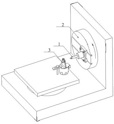
[0025] At present, one of the most common bearing riveting methods in the aviation field is to reserve a special groove on the shell parts and then use steel balls or rollers to roll the ring to close. According to standard requirements, it is necessary to process a groove of corresponding specification around the bearing hole of the shell part before pressing the riveting bearing. The traditional processing method is to customize a special groove tool, use the bearing hole to locate, and then use the boring machine to process the groove with linear feed. However, in this processing method, one groove processing tool can only process one type of bearing hole and one type of groove. No matter the change of the bearing hole or the change of the groove specification, the groove processing tool needs to be re-customized. That is to say, with the above processing method, the groove processing tools have poor versatility and cannot be applied to the processing of the groove features...


PUM


Abstract

The invention discloses a bearing hole groove machining method, which comprises the following steps: clamping a groove machining cutter on a facing head cutter rest, correcting the direction of the cutter, boring a small section of excircle by using the machining cutter to determine the rotation diameter of the cutter and determine the zero position of a U shaft of a facing head, clamping and correcting a part on a machine tool, and finally calling numerical control programs to machine grooves. According to the bearing hole groove machining method, different numerical control programs are compiled, each numerical control program corresponds to the groove of one specification, and the feeding track of the machining cutter is controlled through the numerical control programs, that is, the profile angles of the grooves are controlled. During groove machining, only the corresponding numerical control programs need to be called, and groove features of different specifications can be machined through one machining cutter by means of U and Z interpolation. The bearing hole groove machining method is high in machining efficiency, good in universality and suitable for machining all shell groove features based on the HB 0-37 standard.

Description

technical field [0001] The invention relates to the field of mechanical processing, in particular to a method for processing bearing hole grooves based on a machining center with a flat rotary disk. Background technique [0002] Reserving a special groove on the shell parts and then using steel balls or rollers to roll the ring is a common bearing riveting method based on HB0-37, and it is also one of the most common bearing riveting methods in the aviation field. According to standard requirements, it is necessary to process a groove of corresponding specification around the bearing hole of the shell part before pressing the riveting bearing. The traditional processing method is to customize a special groove tool, use the bearing hole to locate, and then use the boring machine to process the groove in a straight line. In this processing method, a groove processing tool can only process one type of bearing hole and one specification. Grooves, whether bearing bore changes or...

Claims


Application Information

Patent Timeline
IPC IPC(8): B23D79/00
CPCB23D79/00
Inventor 黄振孜肖强张丽娟李尧黄振宇
Owner JIANGXI HONGDU AVIATION IND GRP
Why Eureka
Try Eureka