Silk thread winding roller for textile machinery

A technology for textile machinery and winding rollers, which is applied in the field of silk winding rollers for textile machinery, which can solve the problems of waste of manpower, inconsistent rotation of cylinder rollers, interweaving, etc., and achieve the effects of improving use efficiency, production efficiency, and production efficiency

Inactive Publication Date: 2021-03-09
郑可华
View PDF1 Cites 0 Cited by
  • Summary
  • Abstract
  • Description
  • Claims
  • Application Information

AI Technical Summary

Problems solved by technology

[0004] The object of the present invention is to provide a kind of thread winding roller for textile machinery, in order to solve the problem that the existing thread winding roller for textile machinery proposed in the above-mentioned background technology needs to use a thread roller when winding and concentrating the thread during use. Drum, let the winding roller

Method used


Image

  • Silk thread winding roller for textile machinery
  • Silk thread winding roller for textile machinery
  • Silk thread winding roller for textile machinery

Examples


Embodiment 1

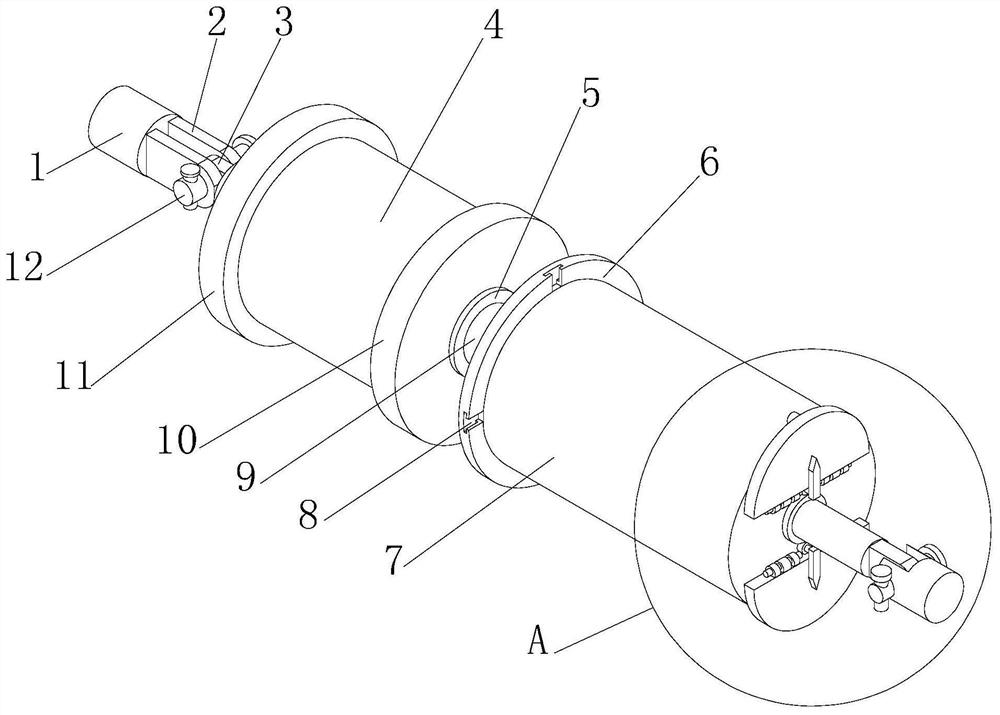
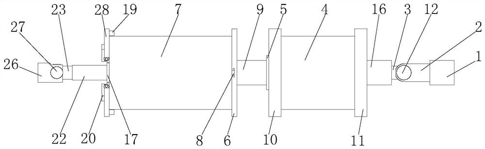
[0030] see Figure 1-7 , the present invention provides a technical solution: a silk winding roller for textile machinery, comprising a first fixed rod 1, a second fixed rod 26 and a roller cylinder 29, one end of the first fixed rod 1 is fixedly mounted with two first The limit hinge plate 2, the inner side of the other end of the two first limit hinge plates 2 is plugged with the first latch shaft 12, the outer side of the first latch shaft 12 is inserted with the second limit hinge plate 3, the second limit hinge plate 3 One end of the hinge plate 3 away from the first latch shaft 12 is fixedly installed with a connecting shaft 16, and the other end of the connecting shaft 16 is fixedly installed with a second limiting plate 11, and the side of the second limiting plate 11 away from the connecting shaft 16 is fixedly installed. There is a rotating electrical machine 4, and the other end of the rotating electrical machine 4 is fixedly installed with a first limiting plate 10...

Embodiment 2

[0033] like Figure 1-7 As shown, on the basis of Embodiment 1, the present invention provides a technical solution: the dimensions of the ball post 34 are compatible with the dimensions of the ball retaining groove 32, and the dimensions of the roller clamp 33 are compatible with the dimensions of the roller clamp. The dimensions of the slot 35 are compatible, the dimensions of the four bayonets 8 are compatible with the dimensions of the four buckles 30, and the positions of the four bayonets 8 and the four buckles 30 are corresponding. The size specification of 19 is compatible with the size specification of the limit hole 36, and the position of the limit rod 19 is corresponding to the position of the limit hole 36.

[0034] In this embodiment, by providing bayonet 8 and buckle 30, when the roller cylinder 29 is replaced, the side of the roller cylinder 29 installed with the first limit ring plate 31 can be sleeved into the outside of the roller column 7, and The buckle 3...

Embodiment 3

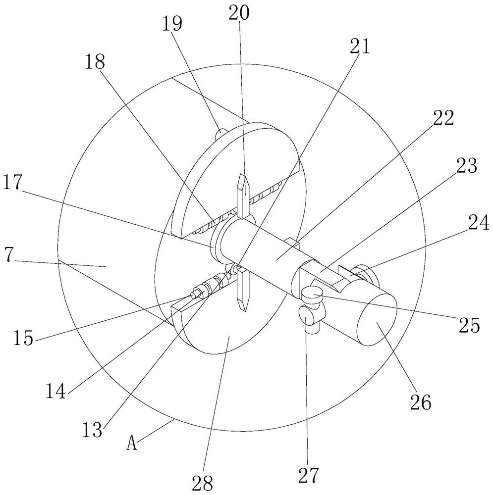
[0036] like Figure 1-7 As shown, on the basis of Embodiment 1 and Embodiment 2, the present invention provides a technical solution: a first limit ring plate 31 is fixedly installed on one end of the roller cylinder 29, and the first limit ring plate 31 is far away from the roller One side of the cylinder 29 is fixedly equipped with four buckles 30, and the other end of the roller cylinder 29 is fixedly equipped with a second spacer ring plate 37, and the side of the second spacer circle plate 37 away from the roller cylinder 29 is provided with a Two limiting holes 36, the outer side of the roller cylinder 29 is provided with a roller clamping groove 35, and the bottom of the roller clamping groove 35 is provided with a parking ball clamping groove 32, and the roller cylinder clamping groove 35 is away from the side of the parking ball clamping groove 32 The side wall of the side wall is hinged with a roller clamp 33, and the bottom of the roller clamp 33 is fixedly equipped...


PUM


Abstract

The invention discloses a silk thread winding roller for textile machinery. The silk thread winding roller for the textile machinery comprises a first fixing rod, a second fixing rod and a roller column barrel, two first limiting hinge plates are fixedly installed at one end of the first fixing rod, and first plug pin shafts are connected to the inner sides of the other ends of the two first limiting hinge plates in an inserted manner; and second limiting hinge plates are inserted into the outer sides of the first plug pin shafts, a connecting shaft is fixedly installed at the ends, away fromthe first plug pin shafts, of the second limiting hinge plates, and a second limiting plate is fixedly installed at the other end of the connecting shaft. Roller clamping plates are clamped into roller clamping grooves, meanwhile, ball columns are clamped into ball stopping clamping grooves to clamp and fix the end point positions of silk threads, then the winding work of the silk threads is started through production operation, and the situation that the silk threads are not tightly connected in the initial winding stage, during subsequent winding operation, the inner layer of a silk thread coil is loosened due to irregular resonance, irregular influences are generated on the position of subsequently wound silk threads, and then the stability of the internal structure is influenced is avoided.

Description

technical field [0001] The invention belongs to the technical field of textile machinery, and in particular relates to a thread winding roller for textile machinery. Background technique [0002] Textile machinery is all kinds of mechanical equipment needed to process natural fibers or chemical fibers into textiles. Although the machinery for producing chemical fibers includes a variety of chemical machinery, it is now considered an extension of textile machinery and belongs to textile machinery in a broad sense. Different fibers such as hemp, silk, wool, etc. require different processes to be processed into textiles, and some are completely different, so the machines required are also various and various. Textile machinery is usually classified according to the production process, including: spinning Yarn equipment, weaving equipment, printing and dyeing equipment, finishing equipment, chemical fiber spinning equipment, silk reeling equipment and non-woven fabric equipment,...

Claims


Application Information

Patent Timeline
IPC IPC(8): B65H54/44B65H67/04B65H75/14B65H75/28B65H75/18B65H54/70
CPCB65H54/44B65H54/70B65H67/0405B65H75/14B65H75/18B65H75/28B65H2701/31
Inventor 郑可华
Owner 郑可华
Why Eureka
Try Eureka