
Automatic glass bead repairing equipment and building construction vehicle

A technology of glass microbeads and microbeads, which is applied in construction, road repair, roads, etc. It can solve the problems that there is no way to repair, and it is difficult for the glass beads to be in a suitable inlay position, so as to achieve the adjustment of the center of gravity and balance adjustment Effect

Inactive Publication Date: 2021-03-09
天津速一腾高新技术有限公司
View PDF0 Cites 0 Cited by
  • Summary
  • Abstract
  • Description
  • Claims
  • Application Information

AI Technical Summary

Problems solved by technology

[0004] The purpose of the present invention is to provide an automatic glass bead repairing equipment and building construction vehicle, so as to alleviate the existing construction technology existing in the prior art that it is difficult to ensure that the glass bead is just in a suitable inlay position, or in other words, when the glass bead The microbeads are solidified after being embedded in the adhesive layer, and there is no way to repair the technical problem

Method used


Image

  • Automatic glass bead repairing equipment and building construction vehicle
  • Automatic glass bead repairing equipment and building construction vehicle
  • Automatic glass bead repairing equipment and building construction vehicle

Examples


Embodiment 1

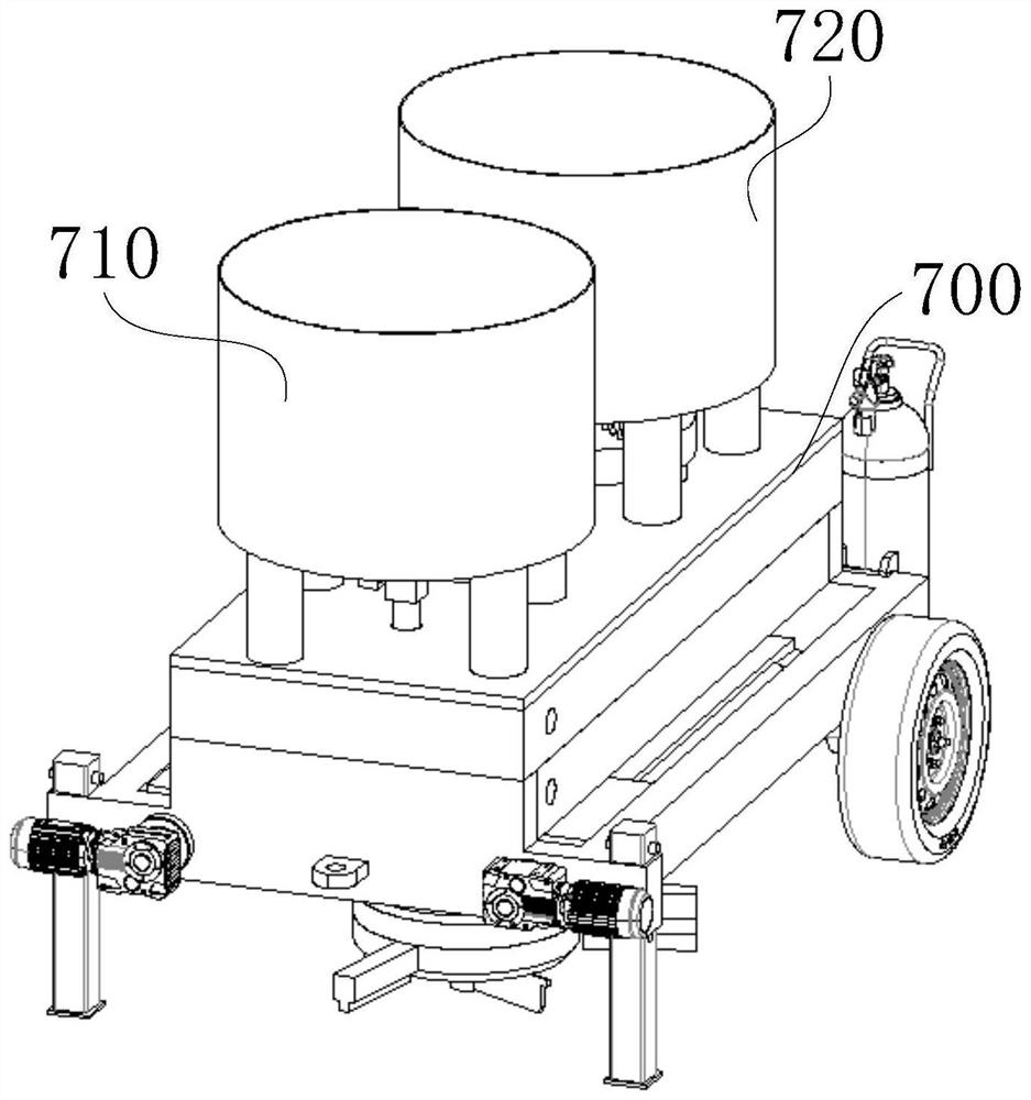
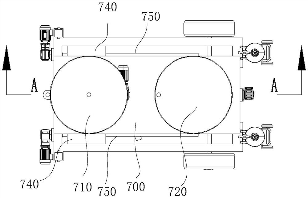
[0074] This embodiment provides a glass bead laying equipment, please refer to Figure 1 to Figure 8 ;include:

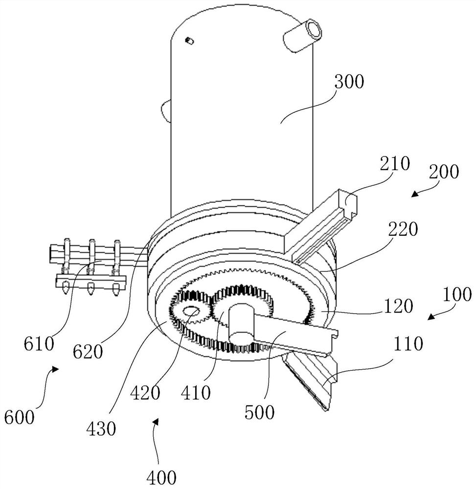
[0075] Microbead laying module 100, adhesive layer laying module 200 and rotating main body 300;

[0076] The bottom surface of the rotating main body 300 is set to be circular, and the bottom surface of the rotating main body 300 is configured as a manhole cover capable of covering the road surface;

[0077] The bead laying module 100 and the adhesive layer laying module 200 are connected to the rotating body 300 and can rotate around the axis of the rotating body 300;

[0078] The micro-bead laying module 100 is provided with a micro-bead discharge head 110, and the lower part of the micro-bead discharge head 110 is provided with a micro-bead discharge port, and the opening of the micro-bead discharge port is opened along the radial direction of the rotating main body 300;

[0079] The adhesive layer laying module 200 is provided with an adhesive layer discharge...

Embodiment 2

[0102] This embodiment provides a glass microbead repair device, please refer to Figure 1 to Figure 8 ,in particular:

[0103] Automated glass bead repair equipment, including:

[0104] Rotating main body 300, bead laying module 100, adhesive layer laying module 200, rotating scraper 500 and melting module 600;

[0105] The bottom surface of the rotating main body 300 is set to be circular and configured as a manhole cover capable of covering the road surface;

[0106] The microbead laying module 100, the adhesive layer laying module 200, the rotating scraper 500 and the melting module 600 are all connected to the rotating body 300 and can rotate around the central axis of the rotating body 300;

[0107] The micro-bead laying module 100 is provided with a micro-bead discharge head 110, and the lower part of the micro-bead discharge head 110 is provided with a micro-bead discharge port, and the opening of the micro-bead discharge port is opened along the radial direction of ...


PUM


Abstract

The invention relates to the field of building construction, and concretely relates to automatic glass bead repairing equipment and a building construction vehicle. The invention aims to solve the problems that in the prior art, it is difficult for an existing construction process to ensure that glass beads are just located at proper inlaying positions, or after the glass beads are embedded into an adhesive layer, along with solidification of the adhesive layer, with repairing cannot be carried out. The equipment comprises a rotating main body, a micro-bead laying module, an adhesive layer laying module, a rotating scraping plate and a melting module, and has the functions of automatic laying, reminding, repairing and the like.

Description

technical field [0001] The invention relates to the field of building construction, in particular to an automatic glass bead repairing equipment and a building construction vehicle. Background technique [0002] In municipal engineering, there are usually sewer manhole covers or other manhole covers (such as cable manhole covers) on the highway. During the day, pedestrians or drivers can notice these manhole covers and adjust the driving path according to the observed situation, but the light is insufficient at night. Therefore, it is difficult for pedestrians or drivers to notice the manhole cover, so it is very inconvenient. [0003] In the existing construction process of glass beads, it is necessary to let the glass beads be partially exposed on the adhesive layer and partially embedded in the adhesive layer. Only in this state can a good reflective effect be achieved, but the existing construction technology is difficult Ensure that the glass beads are just in a suitab...

Claims


Application Information

Patent Timeline
Patent Type & Authority Applications(China)
IPC IPC(8): E01C23/20
CPCE01C23/206
Inventor 鲁春梅
Owner 天津速一腾高新技术有限公司
Learn More