
Residual oil dispersion degree characterization method

A dispersion degree and remaining oil technology, which is applied in earthwork drilling, special data processing applications, wellbore/well components, etc., can solve problems such as the lack of characterization methods for remaining oil dispersion degree, so as to improve the scope of application, ensure versatility, Apply a wide range of effects

Pending Publication Date: 2021-03-09
BC P INC CHINA NAT PETROLEUM CORP +1
View PDF0 Cites 1 Cited by
  • Summary
  • Abstract
  • Description
  • Claims
  • Application Information

AI Technical Summary

Problems solved by technology

[0005] The main purpose of the present invention is to provide a remaining oil dispersion degree characterization method to solve the problem of lack of remaining oil dispersion degree characterization method in the prior art

Method used


Image

  • Residual oil dispersion degree characterization method
  • Residual oil dispersion degree characterization method
  • Residual oil dispersion degree characterization method

Examples


Embodiment 1

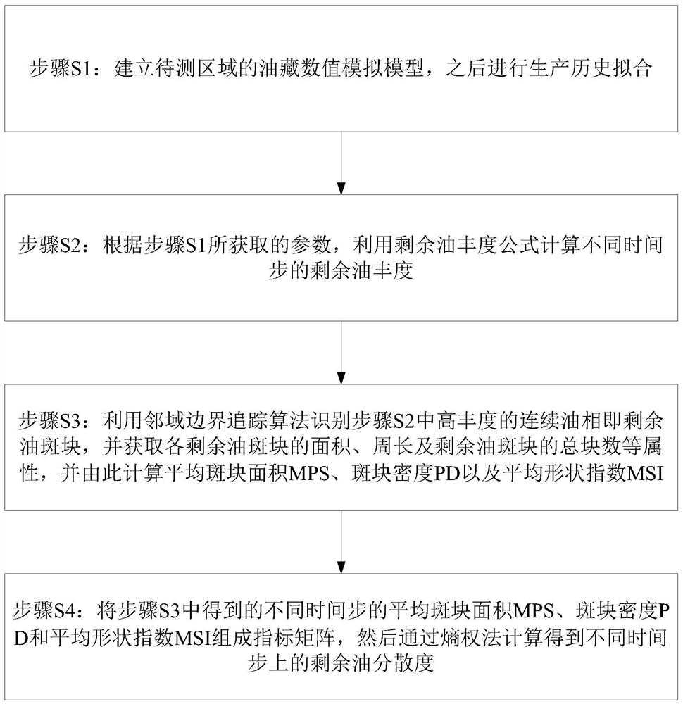
[0060] Such as Figure 2 to Figure 9 As shown, implement step S1: establish the numerical simulation model of the reservoir in the area to be tested, where Table 1 shows the specific parameters of the numerical simulation model of the reservoir.

[0061]

[0062] Table 1

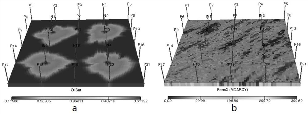
[0063] Such as figure 2 Shown is the reservoir numerical simulation model of the area to be tested, where a represents the distribution of oil wells, and b represents the heterogeneous distribution of permeability.

[0064] Such as image 3 As shown, implement step S2: according to the parameters obtained in step S1, use the remaining oil abundance formula to calculate the remaining oil abundance at different time steps, where, from left to right, they are 1 year of production, 5 years of production and 10 years of production remaining oil abundance.

[0065] Such as Figure 4 As shown, implement step S3: use the neighborhood boundary tracking algorithm to identify image 3 The high-abundance conti...

Embodiment 2

[0072] Such as Figure 10 to Figure 13 Shown is the characterization of remaining oil dispersion of the reservoir numerical simulation model in the area to be tested.

[0073] Such as Figure 10 As shown, the area to be tested is located at the southwest end of the oilfield, which is a semi-anticline structure cut by faults, and the terrain of the whole area is high in the north and low in the south. The structure of the area to be tested is relatively complete, and it belongs to a block with a relatively simple structure among complex fault blocks. The Mapengkou fault develops in the north, extending about 10km. The area to be tested contains four sand layers I, II, III and IV. The average porosity of the reservoir is 28%, which belongs to high porosity reservoir. The average effective permeability of the reservoir is 341mD, which belongs to medium-high permeability reservoir. The average surface crude oil density is 0.85-0.92g / cm 3 , the underground viscosity is 1.2-19.2...


PUM


Abstract

The invention provides a residual oil dispersion degree characterization method. The remaining oil dispersion degree characterization method comprises the steps that S1, an oil reservoir numerical simulation model of a to-be-measured area is established, and then production history fitting is conducted; S2, according to the parameters obtained in the step S1, residual oil abundance of different time steps is calculated through a residual oil abundance formula; S3, the high-abundance continuous oil phase is identified, namely remaining oil patches, in the step S2 by using a neighborhood boundary tracking algorithm, the area and perimeter of each remaining oil patch, the total number of the remaining oil patches and other attributes are obtained, and the average patch area MPS, patch densityPD and average shape index MSI are calculated. and S4, an index matrix is formed by using the average plaque area MPS, the plaque density PD and the average shape index MSI of different time steps obtained in the step S3, and then calculating is performed to obtain the residual oil dispersity of different time steps through an entropy weight method. According to the invention, the problem of lackof a residual oil dispersion degree characterization method in the prior art is solved.

Description

technical field [0001] The invention relates to the technical field of oil and gas exploitation engineering equipment, in particular to a method for characterizing the dispersion degree of remaining oil. Background technique [0002] At present, after decades of development, most oil fields have successively entered high water-cut and ultra-high water-cut periods, and the distribution of remaining oil is highly fragmented. In the middle and late stages of oilfield development, understanding and mastering the distribution of remaining oil in the reservoir is an important basis for reservoir development adjustment. The distribution of remaining oil shows two forms: macroscopic distribution and microscopic distribution. Microscopic remaining oil generally includes two types: one is continuous sheet-like remaining oil occupying more pores, which can be divided into continuous sheet-like remaining oil outside the water-sweeping area and cluster-like remaining oil inside the wate...

Claims


Application Information

Patent Timeline
Patent Type & Authority Applications(China)
IPC IPC(8): E21B49/00G06F30/20
CPCE21B49/00G06F30/20
Inventor 乔岩杨向同张杨王永红侯腾飞尚立涛刘继亮范应璞穆凌雨蒋其辉
Owner BC P INC CHINA NAT PETROLEUM CORP
Learn More