
Self-locking retaining device and retaining method for pipe jacking construction

A backstop device, self-locking technology, applied in mining equipment, shaft equipment, earthwork drilling and mining, etc., can solve problems such as limited effect, no backstop device with adjustable backstop force, unstable soil surface pressure, etc. Achieve the effects of improving the effect, good structural stability, improving construction quality and construction efficiency

Pending Publication Date: 2021-03-09
SHANGHAI TUNNEL ENG CO LTD +1
View PDF5 Cites 1 Cited by
  • Summary
  • Abstract
  • Description
  • Claims
  • Application Information

AI Technical Summary

Problems solved by technology

[0003] In general pipe jacking projects, the thrust of the earth pressure on the pipe jacking head is not large, and shear pins or support rods are generally used to withstand the segment ring of the pipe jacking machine to achieve the purpose of stopping the retreat. In the project, the earth pressure thrust of the pipe jacking machine head is relatively large, and the soil surface pressure is unstable and subsidence will occur. It is necessary to use the thrust adjustment of the backstop device to balance it with the soil surface pressure. In this case, the conventional The anti-retraction device does not have the function of adjusting the anti-retraction force, the effect is limited and it cannot meet the stability requirements of strength and stiffness

Method used


Image

  • Self-locking retaining device and retaining method for pipe jacking construction
  • Self-locking retaining device and retaining method for pipe jacking construction
  • Self-locking retaining device and retaining method for pipe jacking construction

Examples


Embodiment 1

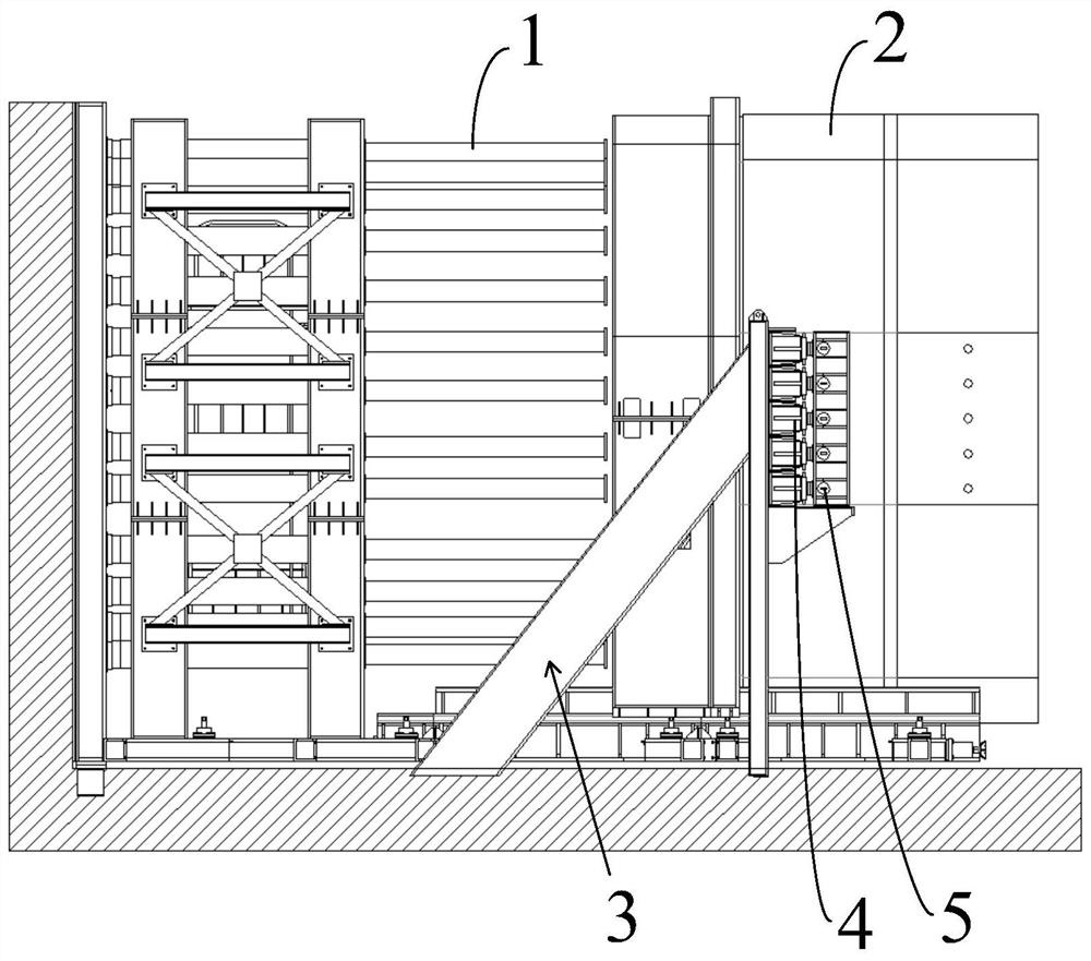
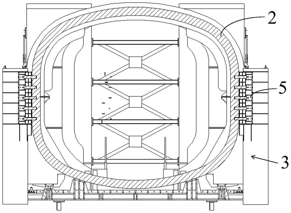
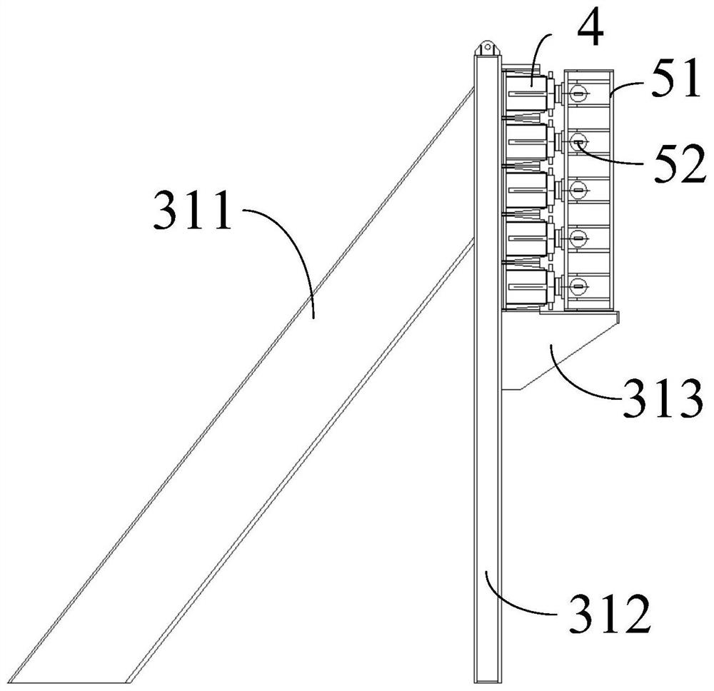
[0037] Such as Figure 1-3 As shown, the self-locking anti-retraction device for pipe jacking construction according to the embodiment of the present invention includes: two sets of anti-retreat brackets 3 installed in the originating shaft, and the two sets of anti-retreat supports 3 are respectively arranged on opposite sides of the segment ring It is arranged along the axial direction of the segment ring; multiple sets of connectors 5 are detachably connected to the segment ring 2; a plurality of mechanical self-locking jacks 4 for pushing the segment ring 2 along the pipe jacking direction are respectively installed on The two sets of backstop brackets 3 are fixedly connected with the connectors one by one; they are used to control the hydraulic control system of the mechanical self-locking jack 4 .

[0038] The two sets of anti-retraction devices are respectively connected to the opposite side walls of the segment ring 2, so that the opposite side walls of the segment rin...

Embodiment 2

[0048] The difference from the first embodiment lies in the structure of the backstop bracket 3 .

[0049] Such as Figure 4-5 As shown, the self-locking anti-retraction device for pipe jacking construction according to the embodiment of the present invention includes:

[0050] Two sets of anti-retraction brackets 3 installed in the originating shaft, the two sets of anti-retraction brackets 3 are respectively arranged on opposite sides of the segment ring and arranged along the axial direction of the segment ring; Connecting piece 5; a plurality of mechanical self-locking jacks 4 used to push the segment ring 2 along the pipe jacking direction, respectively installed on two sets of anti-retraction brackets 3 and fixedly connected with the connecting piece one by one; used to control Hydraulic control system of mechanical self-locking jack 4.

[0051] The two sets of anti-retraction devices are respectively connected to the opposite side walls of the segment ring 2, so that ...


PUM


Abstract

The invention discloses a self-locking retaining device and retaining method for pipe jacking construction, and the retaining device comprises two groups of retaining supports which are installed in an originating well, and the two groups of retaining supports are respectively disposed at two opposite sides of a segment ring and are arranged along the axial direction of the segment ring. The plurality of groups of connecting pieces are detachably connected with the segment ring. The mechanical self-locking jacks are used for pushing the segment rings in the pipe jacking direction, are installed on the two sets of retaining supports respectively and are fixedly connected with the connecting pieces in a one-to-one correspondence mode. The hydraulic control system is used for controlling themechanical self-locking jack. According to the pipe jacking machine segment ring retaining device, the retaining effect of the pipe jacking machine segment ring can be greatly improved, the thrust ofthe retaining device can be accurately adjusted, the thrust and the soil pressure are kept balanced, the retaining thrust can be adjusted, an unbalance loading structure with a certain angle is provided, the structural stability is good, and the construction quality and the construction efficiency are greatly improved.

Description

technical field [0001] The invention relates to the technical field of tunnel construction, in particular to a self-locking anti-backward device and an anti-backward method for pipe jacking construction. Background technique [0002] Pipe jacking machine is a commonly used excavation equipment for underground transportation system construction. Pipe jacking construction is an underground pipeline construction method developed after shield tunneling construction. Pipe jacking construction relies on the main jacking cylinder and the intermediate room between pipelines Push the tool pipe or boring machine from the working well through the soil layer to the receiving well for lifting. The power device of the pipe jacking machine is located in the working well. During the installation of the segment ring, the power supply and pipeline need to be cut off. The pipe jacking head loses power and stops working. The pipe jacking machine and the installed segment ring will open Under t...

Claims


Application Information

Patent Timeline
Patent Type & Authority Applications(China)
IPC IPC(8): E21D9/10E21D11/08E21F17/00
CPCE21D9/10E21D11/08E21F17/00
Inventor 彭世宝杨正袁玮皓黄德中孙骏张弛郑敏洁徐天明陈旭光李钦蒋宏亮王金一施慧俊朱健卢康明陈琦陆杰庄欠伟
Owner SHANGHAI TUNNEL ENG CO LTD
Learn More