Magnetic suspension rotor falling radial protection device

A technology of a magnetic suspension rotor and a protection device, which is applied in the field of magnetic suspension, can solve the problems of limited elastic deformation of rolling bearings, protection of bearing damage, and difficulty in keeping the damping ratio sufficient to keep the bearing, so as to achieve the effect of improving the working range and damping ratio and improving reliability.

Pending Publication Date: 2021-03-09
北京亚之捷动力科技有限公司
View PDF0 Cites 1 Cited by
  • Summary
  • Abstract
  • Description
  • Claims
  • Application Information

AI Technical Summary

Problems solved by technology

However, the rolling element force analysis of rolling bearings generally adopts the Hertzian contact model, which is complex in calculation and poor in accuracy.
The deformation of rolling bearings is also affected by preload during use, and the bearing tracks and rolling body sizes of different manufacturers are also different, which brings great difficulties to design and use
Restricted by the material and volume of the rolling bearing, the elastic deformation of the rolling bearing is also very limited, and the damping ratio is difficult to meet the needs of keeping the bearing, which makes the working range of the rolling bearing-based protection device very narrow
If the bearing stiffness is too high, it will not have a protective effect; if the bearing stiffness is low, it may cause damage to the protective bearing, or even cause greater losses

Method used


Image

  • Magnetic suspension rotor falling radial protection device
  • Magnetic suspension rotor falling radial protection device
  • Magnetic suspension rotor falling radial protection device

Examples


Embodiment 1

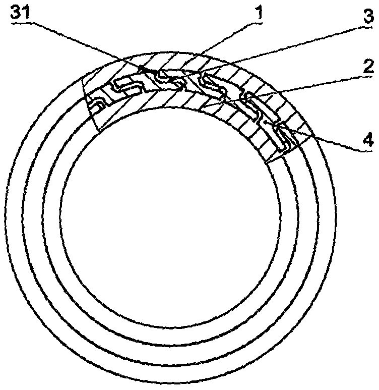
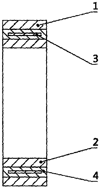
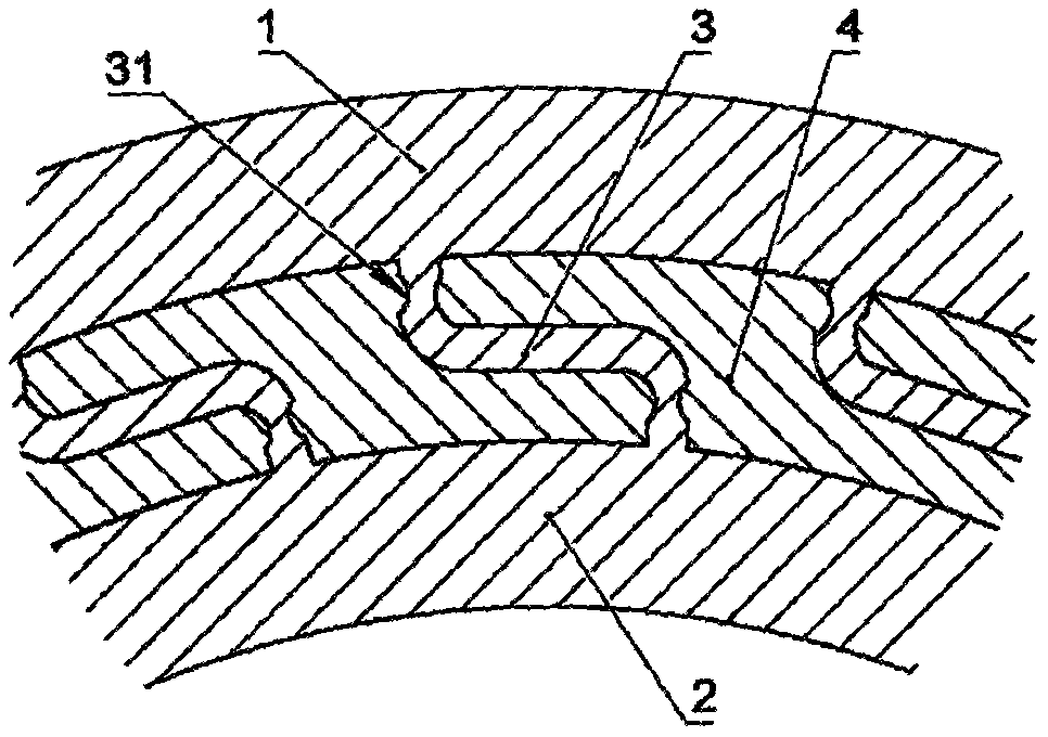
[0033] A magnetic levitation rotor falling radial protection device of the present invention is as follows: figure 1 As shown, the protection ring is integrally processed and formed as a structural part, and the protection ring is composed of the outer ring 1 of the protection ring, the inner ring 2 of the protection ring, the Z-shaped flexible hinge 3, and the damping material 4 . The relative positions of the protection ring outer ring 1 and the protection ring inner ring 2 are coaxial. The Z-shaped flexible hinge 3 is evenly distributed in the circumferential direction between the outer ring 1 and the inner ring 2 of the protection ring, and connects the outer ring 1 and the inner ring 2 of the protection ring.

[0034] The Z-shaped flexible hinge 3 and the damping material 4 determine the performance of the present invention. In the design, finite element analysis technology is used to assist the design. When the deformation is large, an explicit algorithm is used to accur...


PUM


Abstract

The invention discloses a magnetic suspension rotor falling radial protection device. The magnetic suspension rotor falling radial protection device is composed of a protection ring outer ring, a protection ring inner ring, Z-shaped flexible hinges and damping materials, the protection ring outer ring and the protection ring inner ring are connected through the multiple Z-shaped flexible hinges which are evenly distributed in the circumferential direction, and other gaps between the inner ring and the outer ring are filled with the damping materials. The relative positions of the protection ring outer ring and the protection ring inner ring are coaxial, the structural size of the protection ring outer ring is determined according to the shape and size of a bearing hole cooperating with theprotection ring outer ring, and the structural size of the protection ring inner ring can be determined according to the size of a bearing outer ring or a bearing inner hole cooperating with the protection ring inner ring. The magnetic suspension rotor falling radial protection device can cooperate with a rolling bearing to form a magnetic suspension rotor protection device capable of circumferentially rotating, and can directly cooperate and be assembled with an inner ring or an outer ring of the rolling bearing to form a structural form that a protection ring is fixed or the protection ringcan rotate.

Description

technical field [0001] The invention belongs to the technical field of magnetic suspension, and in particular provides a radial protection device for a magnetic suspension rotor falling. Background technique [0002] The magnetic suspension bearing uses magnetic force to make the shaft system and the shaft supporting device rotate in suspension. It has the advantages of no frictional resistance and adjustable operating parameters. Due to the air gap in the operation of the magnetic suspension bearing, when the system is unstable, the rotor will drop and the rotor will hit the supporting structure. [0003] In order to cope with this phenomenon, many inventors have proposed a variety of protective device schemes, most of which are assembled with springs or rubber gaskets between the inner and outer rings to absorb impact energy. Because the speed of the magnetic suspension bearing is generally very high, when the system is abnormal, the rotor will produce a large continuous ...

Claims


Application Information

Patent Timeline
Patent Type & Authority Applications(China)
IPC IPC(8): F16C41/00F16C32/04
CPCF16C32/04F16C41/00
Inventor 夏冰李勇姜鹏
Owner 北京亚之捷动力科技有限公司
Why Eureka
Try Eureka