Voltage sampling circuit of multiple strings of lithium ion batteries

A lithium-ion battery, voltage sampling technology, applied in the direction of measuring current/voltage, measuring electricity, measuring electrical variables, etc. The problem of increasing capacity difference, etc., achieves the effect of accurate measurement data and judgment basis, uniform sampling leakage current, and avoiding voltage and capacity difference.

Pending Publication Date: 2021-03-09
深圳市誉娇诚科技有限公司
View PDF0 Cites 1 Cited by
  • Summary
  • Abstract
  • Description
  • Claims
  • Application Information

AI Technical Summary

Problems solved by technology

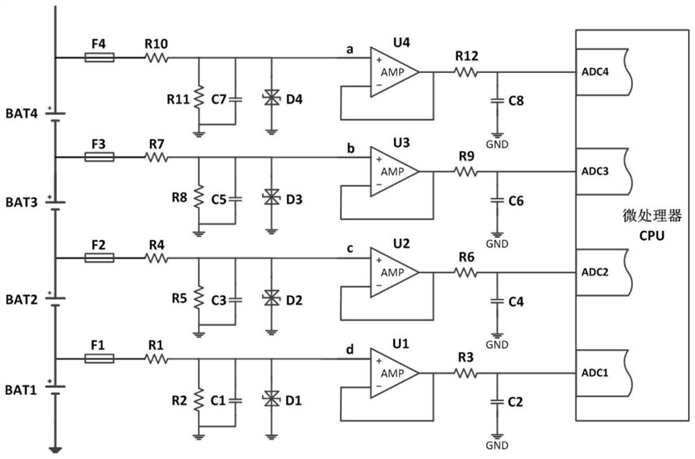
However, there is a serious defect in the method of sampling the voltage of series-connected batteries using a resistor divider circuit. It will cause the sampling leakage current of each single cell in the series-connected battery pack to be different, and the closer to the total negative electrode of the battery pack, the sampling leakage current of the single cell will be different. The greater the leakage current
As time goes by, due to the difference in sampling leakage current, the voltage and capacity differences between individual cells will gradually increase. Over time, the battery pack will fail to be fully charged and discharged, which will seriously affect the energy storage of the battery pack. Backup time and battery life
The technical difficulty in solving the above-mentioned problems of the existing battery voltage sampling method lies in how to realize accurate battery voltage acquisition while avoiding voltage and capacity differences between individual batteries

Method used


Image

  • Voltage sampling circuit of multiple strings of lithium ion batteries
  • Voltage sampling circuit of multiple strings of lithium ion batteries
  • Voltage sampling circuit of multiple strings of lithium ion batteries

Examples


Embodiment Construction

[0019] The following will clearly and completely describe the technical solutions in the embodiments of the present invention with reference to the accompanying drawings in the embodiments of the present invention. Obviously, the described embodiments are only part of the embodiments of the present invention, not all of them. Based on the embodiments of the present invention, all other embodiments obtained by persons of ordinary skill in the art without creative efforts fall within the protection scope of the present invention.

[0020] It should be noted that all directional indications (such as up, down, left, right, front, back...) in the embodiments of the present invention are only used to explain the relationship between the components in a certain posture (as shown in the accompanying drawings). Relative positional relationship, movement conditions, etc., if the specific posture changes, the directional indication will also change accordingly.

[0021] In addition, the ...


PUM


Abstract

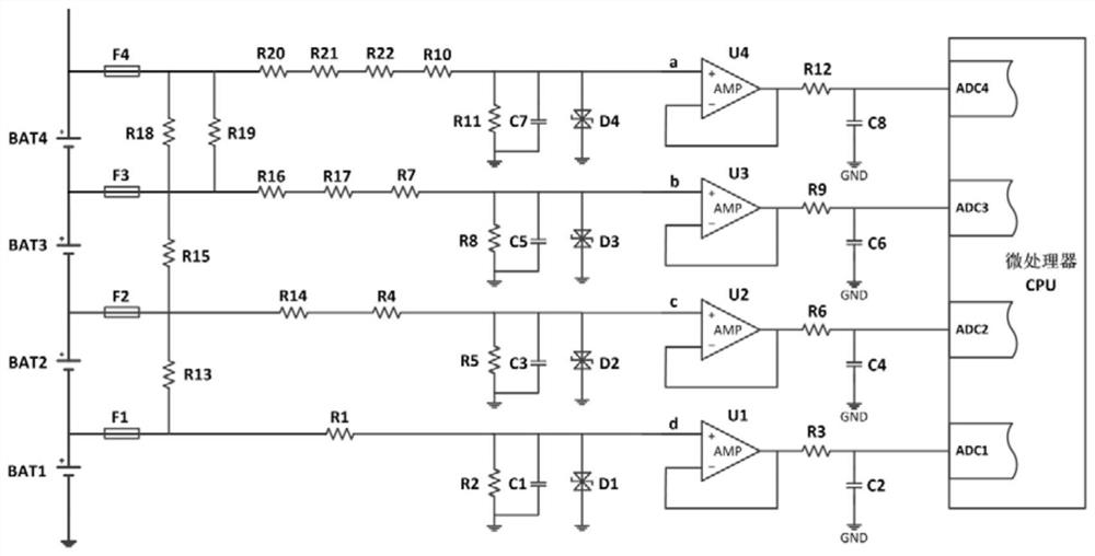
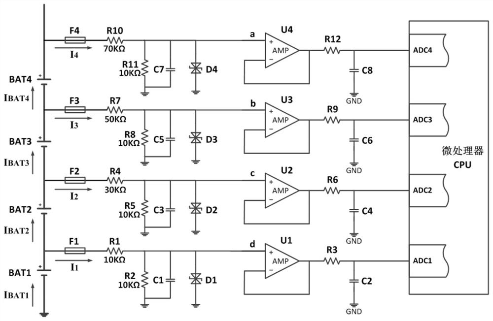
The invention relates to the technical field of lithium ion batteries, and discloses a voltage sampling circuit of multiple strings of lithium ion batteries. The circuit comprises a lithium battery BAT1, a lithium battery BAT2, a lithium battery BAT3, a lithium battery BAT4, a resistor R1, a resistor R2, a resistor R4, a resistor R5, a resistor R7, a resistor R8, a resistor R10, a resistor R11, resistors R13, R15, R18 and R19, a filter capacitor C1, a filter capacitor C3, a filter capacitor C5 and a filter capacitor C7, an analog-to-digital converter ADC1, an analog-to-digital converter ADC2,an analog-to-digital converter ADC3, and an analog-to-digital converter ADC4. The two ends of the resistor R13 are respectively connected with the two ends of the lithium battery BAT2 in parallel, thetwo ends of the resistor R15 are respectively connected with the two ends of the lithium battery BAT3 in parallel, the two ends of the resistor R18 and the two ends of the resistor R19 are respectively connected with the two ends of the lithium battery BAT4 in parallel, and the resistor R13, the resistor R15 and the resistor R19 are connected in series. According to the technical scheme, the problem that sampling leakage currents of all single batteries in a lithium battery pack are inconsistent can be solved, and the phenomenon of battery voltage and capacity difference caused by different sampling leakage currents is effectively avoided.

Description

technical field [0001] The invention relates to the technical field of lithium ion batteries, in particular to a voltage sampling circuit of a multi-string lithium ion battery. Background technique [0002] In recent years, "low-carbon life" and "energy saving and emission reduction" have become the main theme of social life and the most fashionable buzzwords. Under the background of vigorously advocating low-carbon economy and building ecological civilization, the clean The rapid rise of energy has gradually entered our daily life, and is widely used in electric vehicles, home energy storage, power tools, communication base stations, and distributed micro-grids. The internal electrochemical characteristics of lithium-ion batteries are different from those of lead-acid batteries. During the charging and discharging process, the battery voltage must be sampled, monitored, controlled and protected in real time to prevent harmful events such as overvoltage and undervoltage in t...

Claims


Application Information

Patent Timeline
Patent Type & Authority Applications(China)
IPC IPC(8): G01R31/3835G01R31/396G01R19/25
CPCG01R19/2509G01R31/3835G01R31/396
Inventor 彭建华潘继雄周幼华
Owner 深圳市誉娇诚科技有限公司
Why Eureka
Try Eureka