Horizontal spent fuel storage module for nuclear power plant

A technology for spent fuel and nuclear power plants, applied in the field of dry storage of spent fuel for nuclear power plants, which can solve problems such as easy loose overturning, limited site selection conditions, and large footprint, and achieves simple modular assembly and stable seismic structure Good, small footprint effect

Active Publication Date: 2021-03-09
中广核工程有限公司 +3
View PDF11 Cites 4 Cited by
  • Summary
  • Abstract
  • Description
  • Claims
  • Application Information

AI Technical Summary

Problems solved by technology

[0004] However, the existing horizontal concrete modules have at least the following problems: 1) only a single-layer storage mode can be adopted, the scale of spent fuel storage is limited, and the supporting facilities for dry spent fuel storage in nuclear power plants can only be constructed with small-scale storage capacity. It is difficult to guarantee the storage of spent fuel produced in nuclear power plants within 40 to 60 years; 2) It occupies a large area, the site selection conditions are limited, and the public acceptability is low
Although it has also been proposed to store horizontal concrete modules in a stacked form, the stability after stacking is poor, and it is easy to loosen and overturn under earthquake conditions

Method used


Image

  • Horizontal spent fuel storage module for nuclear power plant
  • Horizontal spent fuel storage module for nuclear power plant
  • Horizontal spent fuel storage module for nuclear power plant

Examples


Embodiment Construction

[0041] In order to make the object, technical solution and technical effect of the present invention clearer, the present invention will be further described in detail below in conjunction with specific embodiments. It should be understood that the specific implementations described in this specification are only for explaining the present invention, not for limiting the present invention.

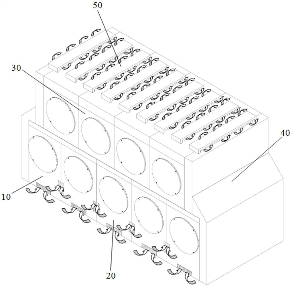
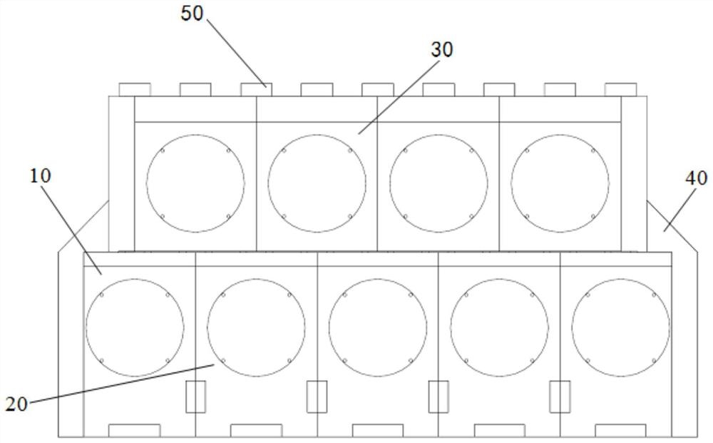
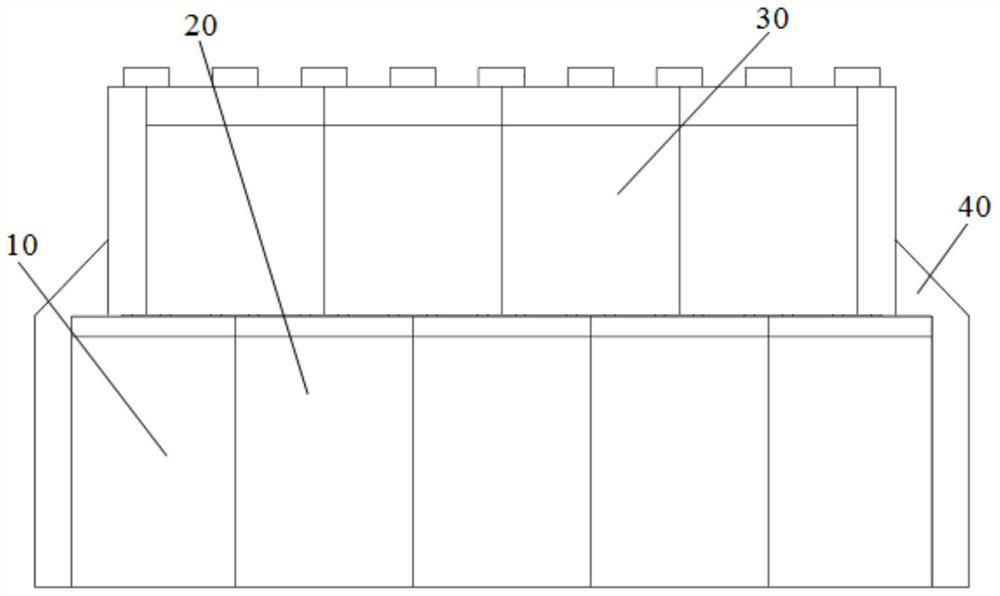
[0042] see Figure 1 to Figure 4 As shown, the nuclear power plant spent fuel horizontal storage module of the present invention includes an upper and lower two-layer structure, and the lower structure includes N ( figure 1 Take N=5 as an example) the lower modules 10 and 20 are independent and arranged side by side, and the upper structure includes N-1 ( figure 1 4 among them) the upper layer modules 30 arranged side by side and interlaced with the lower layer modules 10, 20. The bodies of the upper module 30 and the lower modules 10 , 20 are both hollow cuboid structures, and the botto...


PUM


Abstract

The invention discloses a horizontal spent fuel storage module for a nuclear power plant. A lower-layer structure of the horizontal spent fuel storage module comprises N lower-layer modules which areindependent of one another and are arranged side by side, and an upper-layer structure comprises N-1 upper-layer modules which are arranged side by side and are staggered with the lower-layer modules;main bodies of the upper-layer modules and the lower-layer modules are of hollow cuboid structures; a bottom plate of the upper-layer module clings to a top cover of the lower-layer module; an upper-layer module air inlet is formed in the middle of a bottom plate of the upper-layer module, first meshing plates nested into the upper-layer module air inlet are arranged on the two sides of a top cover of the lower-layer module respectively, a lower-layer module air outlet is formed in the middle of a top cover of the lower-layer module, and second meshing plates nested into the lower-layer module air outlet are arranged on the two sides of the bottom plate of the upper-layer module respectively. A Z-shaped meshing structure is formed between the bottom plate of the upper-layer module and thetop cover of the lower-layer module, and each upper-layer module is meshed and fixed on two adjacent lower-layer modules to form a staggered structure. The horizontal spent fuel storage module has the advantages of being good in stability, easy and convenient to assemble in a modular mode and small in occupied area.

Description

technical field [0001] The invention belongs to the field of dry storage of nuclear power plant spent fuel, and more specifically relates to a nuclear power plant spent fuel horizontal storage module. Background technique [0002] Concrete modules (horizontal and vertical) for dry storage of spent fuel in nuclear power plants are mainly used to store and protect fuel storage tanks sealed with spent fuel assemblies. Perform nuclear safety functions, including: provide structural protection and radiation shielding for spent fuel storage tanks, and provide air convection channels to sufficiently cool spent fuel storage tanks. [0003] At present, the horizontal concrete modules that are widely and maturely used in the world are internal hollow cuboid reinforced concrete structures, including square top seats, concrete hoardings, internal support guide rails and detachable door opening covers. The square top seat and concrete coaming are reinforced concrete structures, which ar...

Claims


Application Information

Patent Timeline
Patent Type & Authority Applications(China)
IPC IPC(8): G21C19/07
CPCG21C19/07Y02E30/30
Inventor 程呈潘跃龙唐邵华张学岭莫怀森
Owner 中广核工程有限公司
Why Eureka
Try Eureka