Low-capacity oil-to-low voltage coil foil winding
A low-voltage coil and small-capacity technology, which is applied in the field of coil foil winding, can solve the problems of small-capacity oil-variable low-voltage coil foil winding, etc., and achieve the effect of good width and avoid manual cutting
- Summary
- Abstract
- Description
- Claims
- Application Information
AI Technical Summary
Problems solved by technology
Method used
Image

Examples
Embodiment 1
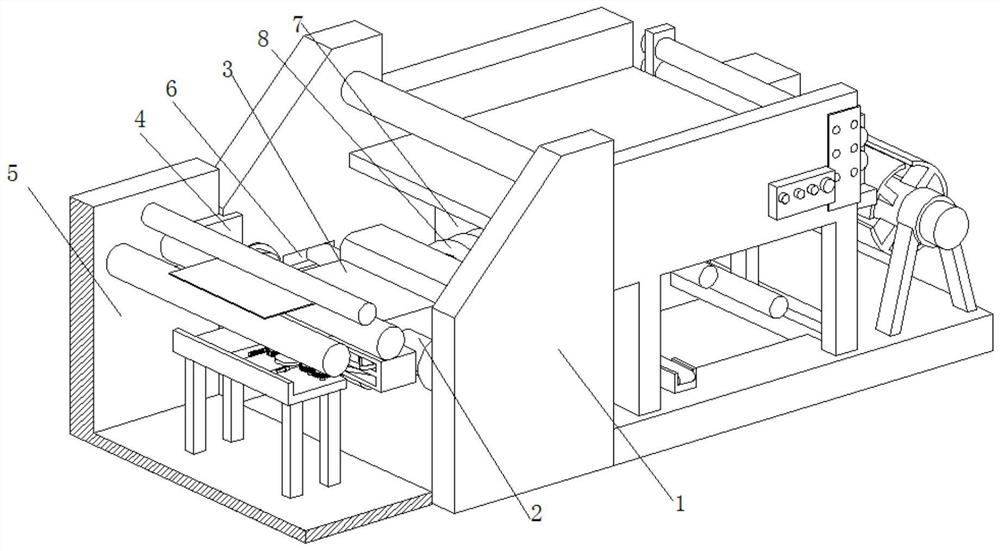
[0035] A small-capacity oil transformer low-voltage coil foil winding, such as Figure 1-Figure 3 As shown, the body 1 is included, the inside of the body 1 is rotatably connected with a winding shaft 2, the surface of the winding shaft 2 is welded with a winding block 3, the front part of the body 1 is clamped with a block 4, and the front part of the block 4 is provided with a Automatic sheet sticking mechanism 5, the inside of body 1 is positioned at the rear portion of bobbin 2 and offers limit groove 6, and the inside of body 1 is positioned at the rear portion of bobbin 2 and is welded with base 7, and the front portion of base 7 is provided with shaping device 8.
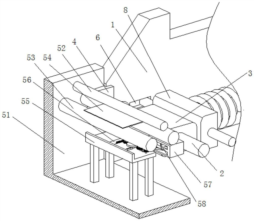
[0036] In this embodiment, the automatic film sticking mechanism 5 includes a moving seat 51, the surface of the moving seat 51 is welded and fixed to the front of the block 4, and the inside of the moving seat 51 is connected to a spray column 52 for rotation, and the moving seat 51 is located at the spraying...
Embodiment 2
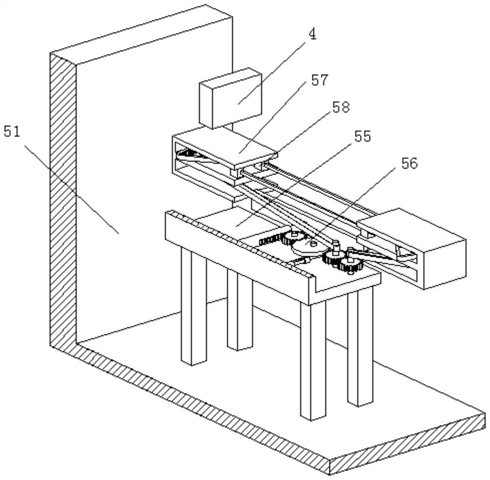
[0038] Such as Figure 4-Figure 7 As shown, the interlocking device 56 includes a rotating shaft 1 561 and a main roller shaft 567. Both ends of the rotating shaft 561 are connected to the interior of the fixed table 55 for rotation. The surface of the rotating shaft 561 is welded with a push gear 562. The left side of the push gear 562 A pusher 563 is arranged on the side, the surface of the pusher gear 562 is meshed with a control half gear 564, the inner rotation of the control half gear 564 is connected with a rotating shaft 2 565, and the surface of the rotating shaft 2 565 is located at the bottom of the control half gear 564, and a starting device 566 is provided. The surface of the main roller shaft 567 is welded with a shearing gear 568, the surface of the shearing gear 568 is meshed with a reverse gear 569, and the inside of the reverse gear 569 is welded with a roller shaft, which passes through the belt and the auxiliary gear inside the right side cutting device 58....
Embodiment 3
[0045] Such as Figure 8 As shown, the shaping device 8 includes a pressing spring 81, the rear end of the pressing spring 81 is welded and fixed to the front portion of the base 7, the front end of the pressing spring 81 is welded with a pressing block 82, and both sides of the pressing block 82 are welded with sliding The arm 83, the surface of the sliding arm 83 is slidingly connected with the inner wall of the limiting groove 6. By setting the shaping device 8, when the winding block 3 rotates and wraps, it is in continuous contact with the pressing block 82, thereby passing through the rear part of the pressing block 82. The impact of the elastic force of the pressing spring 81 achieves the effect of being squeezed, thereby achieving the effect of squeezing and shaping the copper coil wound on the surface of the winding block 3, and further achieving the effect of making the width of the coil better. By setting the sliding arm 83 The surface of the surface is slidingly co...
PUM
 Abstract
Description
Claims
Application Information
 - R&D
- Intellectual Property
- Life Sciences
- Materials
- Tech Scout
- Unparalleled Data Quality
- Higher Quality Content
- 60% Fewer Hallucinations
Browse by: Latest US Patents, China's latest patents, Technical Efficacy Thesaurus, Application Domain, Technology Topic, Popular Technical Reports.
© 2025 PatSnap. All rights reserved.Legal|Privacy policy|Modern Slavery Act Transparency Statement|Sitemap|About US| Contact US: help@patsnap.com