Supercharge Your Innovation With Domain-Expert AI Agents!

Magnetic field drive control micromanipulation system for biological sample

A biological sample, operating system technology, applied in the field of micromanipulation equipment, can solve the problems of long time, difficult to guarantee damage, high operator requirements, etc., to achieve the effect of simple operation, easy operation, and avoidance of damage

Active Publication Date: 2021-03-09
宁波智能装备研究院有限公司
View PDF5 Cites 0 Cited by
  • Summary
  • Abstract
  • Description
  • Claims
  • Application Information

AI Technical Summary

Problems solved by technology

This process requires people to operate under the microscope for a long time, and has high requirements for operators. Generally, it takes more than half a year of professional training, and it often takes several minutes to operate a biological sample.
At the same time, negative pressure is used for suction and transfer. The selection of negative pressure is generally determined based on experience. It is difficult to guarantee that no damage will be caused to biological samples. In addition, it often takes one to two days to make an additional set in order to perform plane posture positioning and fixation. Dedicated agar plate
[0003] In order to solve the above problems, researchers at home and abroad have proposed a variety of solutions. The most common method is to use microfluidic chips for biological sample transmission and attitude adjustment, etc., but it requires special flow channels for different biological samples. And once designed, it can only be aimed at specific tasks, and cannot flexibly adapt to changes in tasks

Method used


Image

  • Magnetic field drive control micromanipulation system for biological sample
  • Magnetic field drive control micromanipulation system for biological sample
  • Magnetic field drive control micromanipulation system for biological sample

Examples


Embodiment Construction

[0024] The following will clearly and completely describe the technical solutions in the embodiments of the present invention with reference to the accompanying drawings in the embodiments of the present invention. Obviously, the described embodiments are only some, not all, embodiments of the present invention. Based on the embodiments of the present invention, all other embodiments obtained by persons of ordinary skill in the art without making creative efforts belong to the protection scope of the present invention.

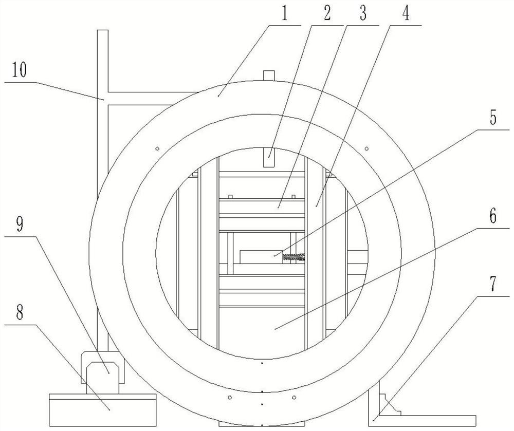
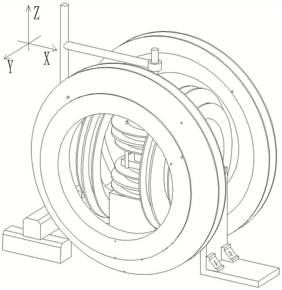
[0025] The purpose of the present invention is to provide a magnetic field-driven control microscopic operating system for biological samples, which can perform micromanipulation on any biological sample subject and any experimental task in biological research.

[0026] In order to make the above objects, features and advantages of the present invention more comprehensible, the present invention will be further described in detail below in conjunction with the ...


PUM


Abstract

The invention relates to a magnetic field drive control micromanipulation system for a biological sample. The magnetic field generator comprises three groups of Maxwell coil assemblies and a coil fixing table for fixing the three groups of Maxwell coil assemblies, and the three groups of coil assemblies are respectively orthogonal; and the imaging system comprises an X-direction moving sliding table and a Y-direction moving sliding table, the support is arranged at the joint of the X-direction moving sliding table and the Y-direction moving sliding table, the electron microscope is arranged onthe support, the supporting table penetrates through the center of the Z-direction Maxwell coil, and the supporting table is located in the Y-direction Maxwell coil set. The electron microscope comprises a biological sample loading and operating table, the biological sample loading and operating table is arranged on the supporting table, the biological sample loading and operating table comprisesa magnetic control robot, and the magnetic control robot selects different structures according to different biological samples and different experimental tasks. According to the invention, micromanipulation can be carried out on any biological sample experiment object and any experiment task in biological research.

Description

technical field [0001] The invention relates to the technical field of micromanipulation equipment, in particular to a magnetic field-driven control micromanipulation system for biological samples. Background technique [0002] In the micromanipulation of biological samples, it is usually necessary to perform large-scale high-throughput injection, observation, and measurement of mechanical properties of tiny biological samples, and it is usually necessary to transfer the biological samples to the corresponding position and carry out these operations. Posture adjustment, fixation, etc. for injection, observation, and measurement of specific organs. In the traditional manual operation, the general operator uses a glass tube to generate negative pressure to absorb the organism, and then places it in the agar plate made according to the requirements of different biological samples to position and fix the plane biological sample posture, and finally perform various injection oper...

Claims


Application Information

Patent Timeline
Patent Type & Authority Applications(China)
IPC IPC(8): H01J37/26
CPCH01J37/261H01J37/265
Inventor 于兴虎黄港
Owner 宁波智能装备研究院有限公司
Features
  • R&D
  • Intellectual Property
  • Life Sciences
  • Materials
  • Tech Scout
  • Unparalleled Data Quality
  • Higher Quality Content
  • 60% Fewer Hallucinations
Learn More