A radio frequency connector with lightning protection function
A technology for radio frequency connectors and cable connectors, which is applied in the direction of connection, high frequency structural connection, and components of connecting devices, etc., can solve the problems of the influence of surrounding electronic components, increase the total investment of equipment, and be vulnerable to lightning strikes, etc. Achieve the effect of preventing lightning strikes, making up for high density and convenient connection
- Summary
- Abstract
- Description
- Claims
- Application Information
AI Technical Summary
Problems solved by technology
Method used
Image
Examples
Embodiment 1
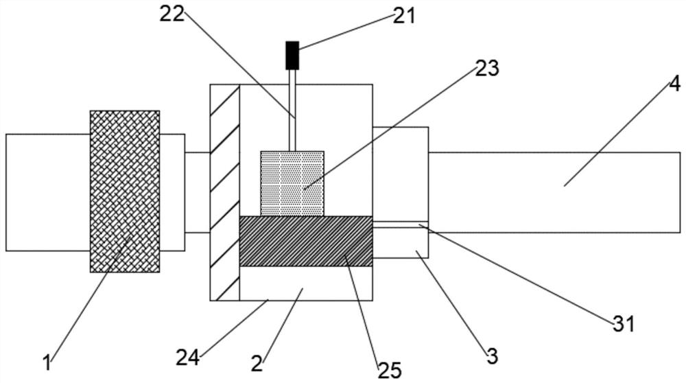
[0038] A radio frequency connector with lightning protection function, including a radio frequency connector 1, a lightning protection device 2 and a cable connector 3 connected in sequence from left to right; the lightning protection device 2 includes a lightning receptor 21, a conductive Body 22 and lightning protection circuit 23.
[0039] The lightning protection circuit 23 is provided with an ordinary resistor, a piezoresistor, a gas discharge tube, a light emitting diode and a transient voltage suppression diode which are sequentially connected by wires.
[0040] The conductor 22 is one of copper wire, aluminum wire and copper-nickel alloy wire; the surface of the conductor 22 is coated with a first insulating and protective coating.
[0041] A shielding protection shell 24 is installed on the outer surface of the lightning protection device 2 , and the lightning receptor 21 is installed outside the shielding protection shell 24 .
[0042] The lightning protection devic...
Embodiment 2
[0060] A radio frequency connector with lightning protection function, including a radio frequency connector 1, a lightning protection device 2 and a cable connector 3 connected in sequence from left to right; the lightning protection device 2 includes a lightning receptor 21, a conductive Body 22 and lightning protection circuit 23.
[0061] The lightning protection circuit 23 is provided with an ordinary resistor, a piezoresistor, a gas discharge tube, a light emitting diode and a transient voltage suppression diode which are sequentially connected by wires.
[0062] The conductor 22 is one of copper wire, aluminum wire and copper-nickel alloy wire; the surface of the conductor 22 is coated with a first insulating and protective coating.
[0063] A shielding protection shell 24 is installed on the outer surface of the lightning protection device 2 , and the lightning receptor 21 is installed outside the shielding protection shell 24 .
[0064] The lightning protection devic...
Embodiment 3
[0082] A radio frequency connector with lightning protection function, including a radio frequency connector 1, a lightning protection device 2 and a cable connector 3 connected in sequence from left to right; the lightning protection device 2 includes a lightning receptor 21, a conductive Body 22 and lightning protection circuit 23.
[0083] The lightning protection circuit 23 is provided with an ordinary resistor, a piezoresistor, a gas discharge tube, a light emitting diode and a transient voltage suppression diode which are sequentially connected by wires.
[0084] The conductor 22 is one of copper wire, aluminum wire and copper-nickel alloy wire; the surface of the conductor 22 is coated with a first insulating and protective coating.
[0085] A shielding protection shell 24 is installed on the outer surface of the lightning protection device 2 , and the lightning receptor 21 is installed outside the shielding protection shell 24 .
[0086] The lightning protection devic...
PUM
 Abstract
Description
Claims
Application Information
 - R&D
- Intellectual Property
- Life Sciences
- Materials
- Tech Scout
- Unparalleled Data Quality
- Higher Quality Content
- 60% Fewer Hallucinations
Browse by: Latest US Patents, China's latest patents, Technical Efficacy Thesaurus, Application Domain, Technology Topic, Popular Technical Reports.
© 2025 PatSnap. All rights reserved.Legal|Privacy policy|Modern Slavery Act Transparency Statement|Sitemap|About US| Contact US: help@patsnap.com

