Air separation system, method for low-temperature separation of air by means of an air separation system, and method for creating an air separation system

A technology of air separation and equipment, which is applied in the direction of cold treatment separation, lighting and heating equipment, refrigeration and liquefaction, etc., can solve the problems of high labor cost and increased cost of air separation equipment, and achieve the effect of avoiding the cost of pipeline laying

Active Publication Date: 2021-03-09
ลินเดอ จีเอ็มบีเอช (นิติบุคคลจัดตั้งขึ้นตามกฎหมายแห่งสหพันธ์สาธารณรัฐเยอรมนี)
View PDF5 Cites 0 Cited by
  • Summary
  • Abstract
  • Description
  • Claims
  • Application Information

AI Technical Summary

Problems solved by technology

This is disadvantageous for various reasons, mainly because no corresponding personnel are available at the target location or labor costs are high
The cost of creating the corresponding air separation plant thus increases significantly

Method used


Image

  • Air separation system, method for low-temperature separation of air by means of an air separation system, and method for creating an air separation system
  • Air separation system, method for low-temperature separation of air by means of an air separation system, and method for creating an air separation system
  • Air separation system, method for low-temperature separation of air by means of an air separation system, and method for creating an air separation system

Examples


Embodiment Construction

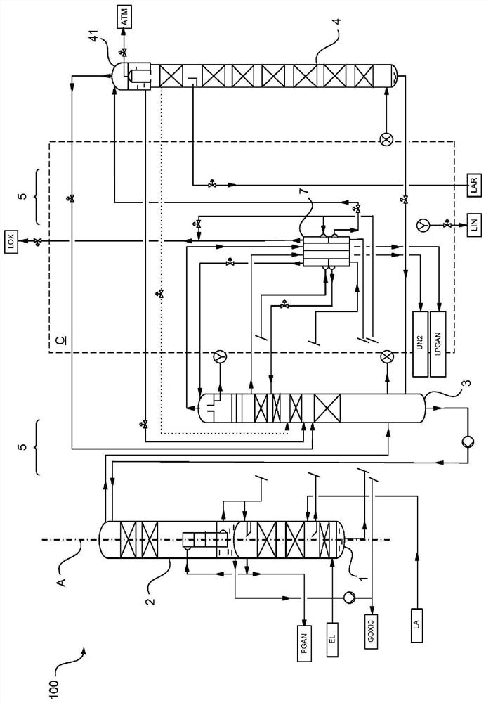
[0052] exist figure 1 An air separation plant according to an embodiment of the present invention is shown in schematic form in . The air separation plant is designated 100 as a whole. figure 1 The spatial arrangement of the components shown in is not in accordance with the invention, the components are here shown side by side in side view.

[0053] As separation unit, the air separation plant 100 has in the form of a high-pressure column 1, a bottom section 2 of a low-pressure column designed in two parts, a top section 3 of a low-pressure column designed in two parts and an argon extraction designed in one piece Four separation units for column 4. The high-pressure column 1 and the base section 2 of the two-part low-pressure column are connected to each other on the housing side. The high-pressure column 1 , the bottom section 2 of the low-pressure column designed in two parts, the top section 3 of the low-pressure column designed in two parts and the argon extraction c...


PUM


Abstract

The invention relates to an air separation system (100) comprising four separation units (1-4) which are connected to one another at least partially by means of lines (5) and / or are connected to one or more further devices (6-8) at least partially by means of lines (5). According to the invention, at least the majority of line sections of the lines (5) running parallel to longitudinal axes (A) ofthe separation units (1-4) are arranged in a compartment (C) in the form of a separately transportable structural unit, and, when viewed as a layout planfrom above perpendicular toalong the longitudinal axes of the separation units (1-4), the compartment (C) and the separation units (1-4) are arranged in four quadrants (Q1-Q4). The separation units (1-4) are either arranged in a cold box (20) without the compartment (C), which cold box has a recess in the fourth quadrant (Q4) in the layout plan viewwhen viewed from above, in which the compartment (C) is arranged in the layout plan viewwhen viewed from above, or the separation units (1-4) are arranged in a cold box with the compartment (C), which cold box has the rectangular cross-section in the layout plan viewwhen viewed from above, wherein the compartment (C) is arranged in a corner of the cold box in the layout plan viewwhen viewed from above. The invention also relates to a corresponding method for the low-temperature separation ofair and a method for creating a corresponding air separation system (100).

Description

[0001] The invention relates to an air separation plant, a method for the cryogenic separation of air by means of a corresponding air separation plant and a method for creating a corresponding air separation plant. Background technique [0002] The production of liquid or gaseous air products by cryogenic separation of air in an air separation plant is known and for example in Wiley-VCH Publishing Company 2006 by H.-W. Edited and published in the book "Industrial Gases Processing", especially described in chapter 2.2.5 "Cryogenic Rectification". [0003] The air separation plant has a rectification column system which can be designed, for example, as a two-column system, in particular a typical Linde two-column system, but also a three-column or multi-column system. In addition to rectification columns for the extraction of liquid and / or gaseous nitrogen and / or oxygen, i.e. for the separation of nitrogen and oxygen, rectification columns for the extraction of other air compon...

Claims


Application Information

Patent Timeline
IPC IPC(8): F25J3/04
CPCF25J3/0409F25J3/04412F25J3/04678F25J3/04727F25J3/04878F25J3/0489F25J2235/02
Inventor 斯特凡·洛克纳
Owner ลินเดอ จีเอ็มบีเอช (นิติบุคคลจัดตั้งขึ้นตามกฎหมายแห่งสหพันธ์สาธารณรัฐเยอรมนี)
Why Eureka
Try Eureka