Medical movable denture mold manufacturing equipment
A removable denture, medical technology, applied in medical science, dentistry, dental prosthesis, etc., can solve problems such as no better
- Summary
- Abstract
- Description
- Claims
- Application Information
AI Technical Summary
Problems solved by technology
Method used
Image
Examples
specific Embodiment approach 1
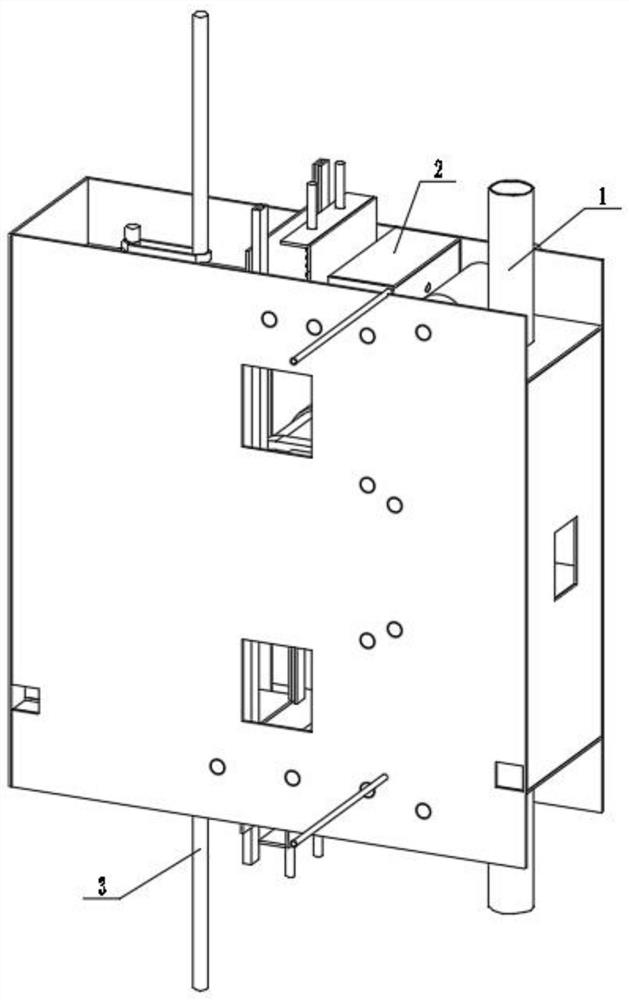
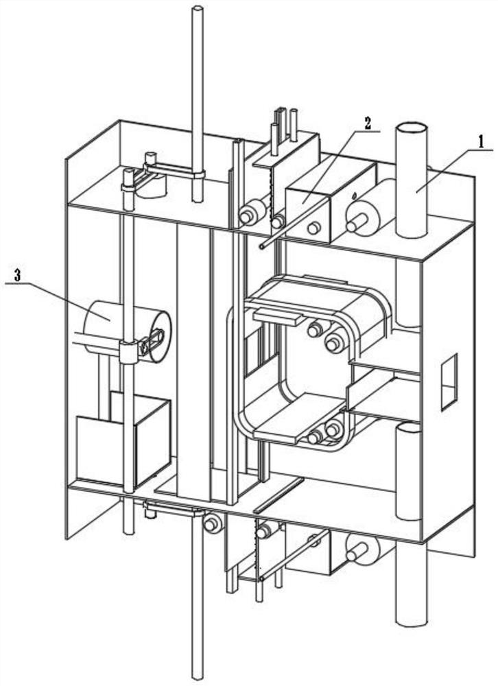
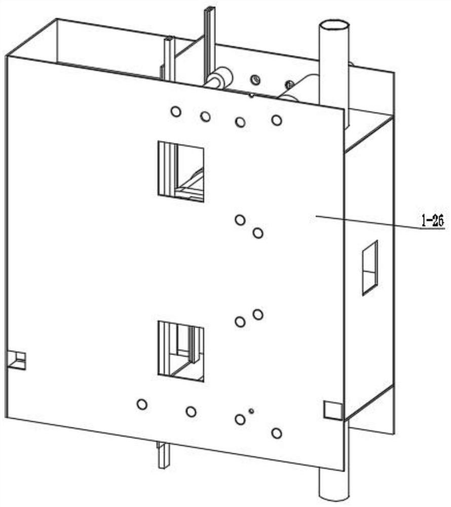
[0029] Combine below figure 1 , figure 2 , image 3 , Figure 4 , Figure 5 , Image 6 , Figure 7 , Figure 8 , Figure 9 , Figure 10 , Figure 11 , Figure 12 , Figure 13 To illustrate this embodiment, the present invention relates to a sampling device, more specifically, a medical movable denture mold manufacturing device, including a linkage hot-pressing mechanism 1, a linkage spraying mechanism 2, and a recovery hot-pressing mechanism 3. The equipment can press the denture The positive film of the mold is pressed into the outer cavity of the female mold, the equipment can accelerate the deformation of the outer cavity of the female mold, the equipment can spray the paint of the female mold to the outer cavity of the female mold, and the equipment can suppress the outer cavity of the female mold to make it smooth.
[0030] The interlocking hot pressing mechanism 1 is connected with the interlocking spraying mechanism 2 , and the recovery hot pressing mechanis...
specific Embodiment approach 2
[0032] Combine below figure 1 , figure 2 , image 3 , Figure 4 , Figure 5 , Image 6 , Figure 7 , Figure 8 , Figure 9 , Figure 10 , Figure 11 , Figure 12 , Figure 13 Describe this embodiment, this embodiment will further explain the first embodiment, the linkage hot pressing mechanism 1 includes a motor 1-1, a motor shaft 1-2, a belt a1-3, a connecting shaft a1-4, and a belt b1-5 , friction wheel 1-6, slide bar 1-7, slide limit plate 1-8, slide rail a1-9, slide rail b1-10, slide rail connecting plate a1-11, slide rail connecting plate b1-12, heat Pressing plate a1-13, linkage friction wheel 1-14, connecting shaft b1-15, belt c1-16, connecting shaft c1-17, lifting friction wheel 1-18, lifting heating tube 1-19, electric heater 1-20, Connecting plate a1-21, connecting plate b1-22, connecting plate c1-23, connecting plate d1-24, connecting plate e1-25, connecting plate f1-26, motor 1-1 is connected with motor shaft 1-2, motor shaft 1-2 is frictionally conne...
specific Embodiment approach 3
[0034] Combine below figure 1 , figure 2 , image 3 , Figure 4 , Figure 5 , Image 6 , Figure 7 , Figure 8 , Figure 9 , Figure 10 , Figure 11 , Figure 12 , Figure 13Describe this embodiment. This embodiment will further explain Embodiment 1. The linkage spraying mechanism 2 includes linkage friction wheel 1 2-1, linkage shaft 1 2-2, belt 1 2-3, and linkage shaft 2 2-4. , helical gear a2-5, helical gear b2-6, propeller connecting shaft 2-7, propeller 2-8, mounting plate a2-9, mounting plate b2-10, mounting plate c2-11, belt 2-12, lift Painting friction wheel 2-13, linkage shaft three 2-14, lift painting plate a2-15, lift painting plate b2-16, reset shaft 2-17, reset limit plate 2-18, return spring 2-19, nozzle 2 -20, linkage friction wheel one 2-1 is frictionally connected with sliding bar 1-7, linkage shaft one 2-2 is connected with linkage friction wheel one 2-1, belt one 2-3 is frictionally connected with linkage shaft one 2-2, Linkage shaft two 2-4 is...
PUM
 Abstract
Description
Claims
Application Information
 - R&D
- Intellectual Property
- Life Sciences
- Materials
- Tech Scout
- Unparalleled Data Quality
- Higher Quality Content
- 60% Fewer Hallucinations
Browse by: Latest US Patents, China's latest patents, Technical Efficacy Thesaurus, Application Domain, Technology Topic, Popular Technical Reports.
© 2025 PatSnap. All rights reserved.Legal|Privacy policy|Modern Slavery Act Transparency Statement|Sitemap|About US| Contact US: help@patsnap.com


