Coal magnetic separation system and method
A technology for coal and magnetic separation, which is applied in chemical instruments and methods, cleaning methods and utensils, cleaning methods using liquids, etc., and can solve problems such as inability to magnetically separate coal
- Summary
- Abstract
- Description
- Claims
- Application Information
AI Technical Summary
Problems solved by technology
Method used
Image

Examples
specific Embodiment approach 1
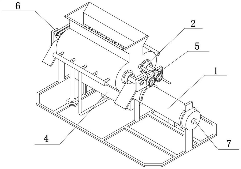
[0035] Combine below Figure 1-10 Description of this embodiment, the coal magnetic separation system includes an outer frame assembly 1, a crushing assembly 2, a drive assembly 3, a cycle cleaning assembly 4, a reciprocating transmission assembly 5, a magnetic separation assembly 6 and a transmission assembly 7, the crushing assembly 2 There are two, the two crushing assemblies 2 are rotatably connected to the outer frame assembly 1, the two crushing assemblies 2 are engaged with each other for transmission, the driving assembly 3 is fixedly connected to the left side of the outer frame assembly 1, and the driving assembly 3 and one of the grinding assemblies The crushing assembly 2 is engaged in transmission, the cleaning assembly 4 is fixedly connected to the outer frame assembly 1, the reciprocating transmission assembly 5 is fixedly connected to the outer frame assembly 1, the reciprocating transmission assembly 5 and one of the crushing assemblies 2 are engaged in transmi...
specific Embodiment approach 2
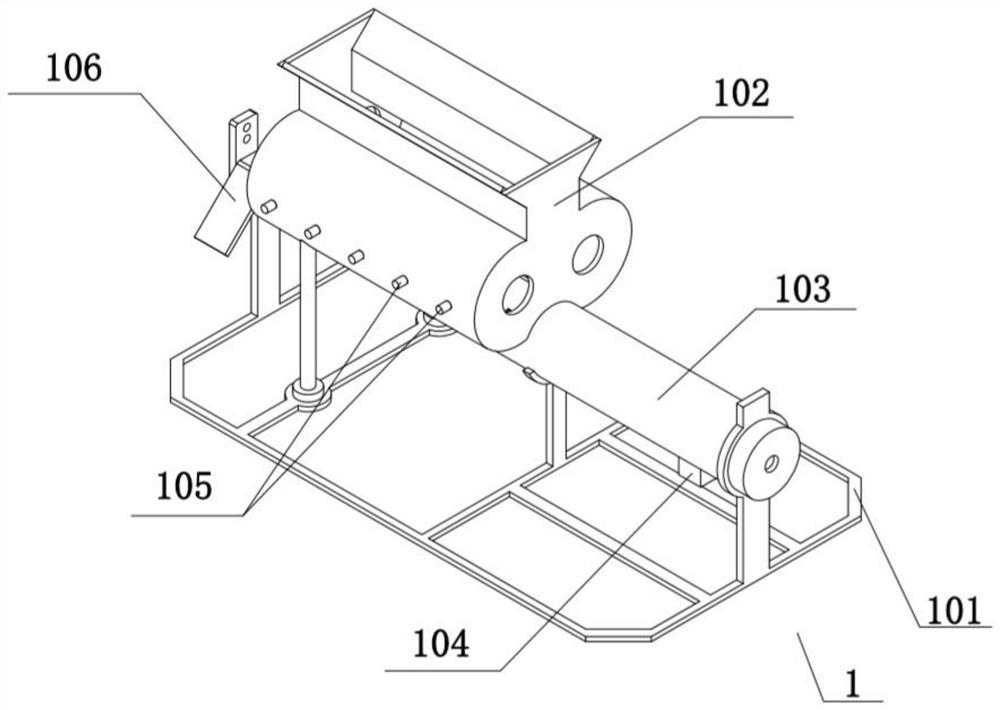
[0038] Combine below Figure 1-10 To illustrate this embodiment, the outer frame assembly 1 includes a bracket 101, a processing box 102, a transfer box 103, a blanking box 104, a cleaning nozzle 105, a first material guide plate 106, a left vertical plate 107, and a water hole 108. The processing box 102 is fixedly connected on the support 101, the lower end of the processing box 102 is fixedly connected with the transmission box 103, the transmission box 103 is fixedly connected with the right side of the support 101, the right side of the transmission box 103 is fixedly connected with the blanking box 104, the processing box 102 Both front and rear sides are fixedly connected with a plurality of cleaning nozzles 105, the left vertical plate 107 is fixedly connected on the left side of the support 101, the first material guide plate 106 is fixedly connected on the left vertical plate 107, and the lower end of the transfer box 103 is evenly distributed with multiple A water h...
specific Embodiment approach 3
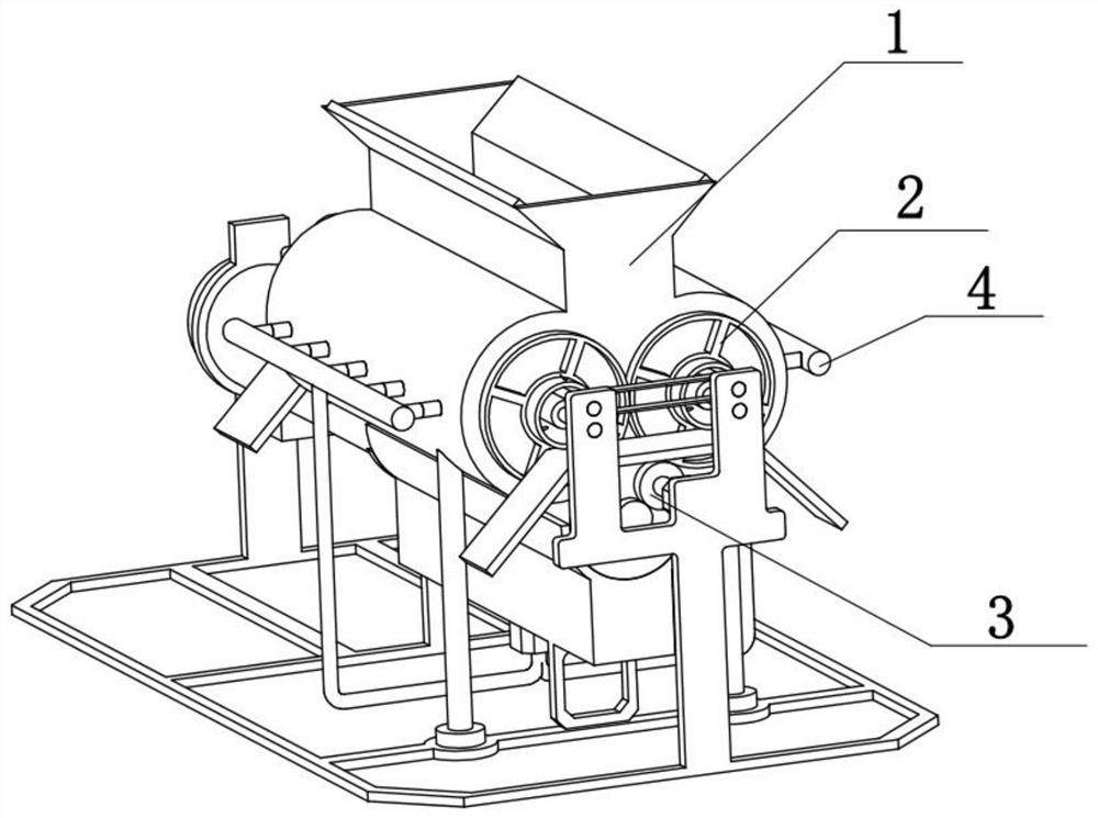
[0040] Combine below Figure 1-10 To illustrate this embodiment, the crushing assembly 2 includes a crushing roller 201, a flow hole 202, a crushing gear 203, an output gear 204, and a magnetic separation chamber 205, and a flow hole 202 is evenly distributed on the crushing roller 201, and the crushing The gear 203 is fixedly connected to the left side of the crushing roller 201, and the output gear 204 is fixedly connected to the right side of the crushing roller 201. The magnetic separation chamber 205 is arranged in the crushing roller 201, and the two crushing rollers 201 are all rotatably connected in the processing Inside the box 102, two crushing gears 203 are meshed with each other for transmission.
[0041] Start the drive motor 301, the drive motor 301 drives the motor gear 302 to rotate, the drive motor 301 meshes and drives one of the crushing rollers 201 to rotate, and the crushing roller 201 drives its corresponding crushing gear 203 and output gear 204 to rotat...
PUM
 Abstract
Description
Claims
Application Information
 - R&D
- Intellectual Property
- Life Sciences
- Materials
- Tech Scout
- Unparalleled Data Quality
- Higher Quality Content
- 60% Fewer Hallucinations
Browse by: Latest US Patents, China's latest patents, Technical Efficacy Thesaurus, Application Domain, Technology Topic, Popular Technical Reports.
© 2025 PatSnap. All rights reserved.Legal|Privacy policy|Modern Slavery Act Transparency Statement|Sitemap|About US| Contact US: help@patsnap.com