Automatic rejecting device

A rejecting device and automatic technology, which is applied in the field of automation, can solve the problems of poor rejecting effect, achieve good rejecting effect, concentrate force, and prevent loose connection

Pending Publication Date: 2021-03-12
长兴普思泰克智能装备有限公司
View PDF0 Cites 1 Cited by
  • Summary
  • Abstract
  • Description
  • Claims
  • Application Information

AI Technical Summary

Problems solved by technology

[0003] The present invention provides an automatic rejecting device with good rejecting effect in order to overcome the deficiency of poor rejecting effect in the prior art

Method used


Image

  • Automatic rejecting device
  • Automatic rejecting device

Examples


Embodiment Construction

[0018] The present invention will be further described below in conjunction with the accompanying drawings and specific embodiments.

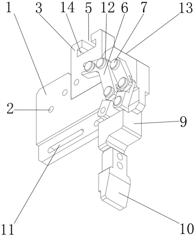
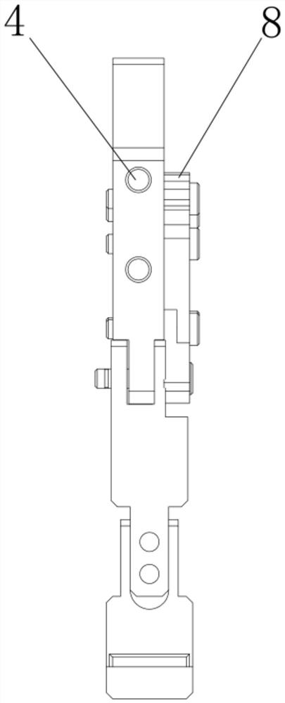
[0019] Such as figure 1 with figure 2 In the shown embodiment, an automatic rejecting device includes a device body 1, a joint assembly and a connecting assembly. The device body 1 is provided with a number of through holes 1, and the joint assembly is provided with a number of through holes 2. One end of the connecting assembly It is connected to the device body 1 through the through hole 1, and the other end of the connecting component is connected to the joint component through the through hole 2. The device body 1 is provided with a jaw 3, and the front end of the device body 1 is provided with an air hole 4, and the inside of the jaw 3 A clamping groove 5 is provided, and the connection assembly includes a connecting piece 6, a fixing column 7 and a fixing ring 8, and the fixing column 7 is connected with the connecting piece 6, the thro...


PUM


Abstract

The invention discloses an automatic rejecting device, and aims to provide an automatic rejecting device with a good rejecting effect. The device comprises a device body, a joint assembly and a connecting assembly, a plurality of first through holes are formed in the device body, a plurality of second through holes are formed in the joint assembly, one end of the connecting assembly is connected with the device body through the first through holes, the other end of the connecting assembly is connected with the joint assembly through the second through holes, a clamping jaw is arranged at the upper end of the device body, and an air hole is formed in the front end of the device body. The automatic rejecting device has the beneficial effects that the rejecting effect is good, force exerted by the device is more concentrated, firm connection between components is facilitated, the length of a joint can be controlled, the front-back position of the joint can be adjusted, loose connection between the components is prevented, and clamping jaw sliding is avoided.

Description

technical field [0001] The invention relates to the technical field of automation, in particular to an automatic rejecting device. Background technique [0002] The automatic removal device is mainly aimed at the removal of unqualified bottle caps. It is an executive device that uses compressed air as power to clamp or remove workpieces. Its main function is to replace human grasping or removal work, which can effectively improve production. Efficiency and safety of work, the automatic rejecting device generally drives the crank through the pneumatic piston arranged inside it, and the crank action drives the gripper to realize the action of clamping or rejecting, but the automatic rejecting device of the current prior art, in the bottle cap During the operation of the test, air blowing is used to remove unqualified products, and the position of the air hole is not reasonable enough. This method will make the bottle cap contaminated with dust, resulting in poor removal effect...

Claims


Application Information

Patent Timeline
Patent Type & Authority Applications(China)
IPC IPC(8): B07C5/36
CPCB07C5/362
Inventor 胡正义
Owner 长兴普思泰克智能装备有限公司
Why Eureka
Try Eureka