Building reinforcing steel bar cut-off device

A cutting device and a technology for building steel bars, which are applied in the field of building steel bar cutting devices, can solve the problems of inconvenient adjustment of the places where steel bars are to be cut off, etc.

Inactive Publication Date: 2021-03-12
ZHEJIANG GUANGSHA COLLEGE OF APPLIED CONSTRTECH
View PDF1 Cites 2 Cited by
  • Summary
  • Abstract
  • Description
  • Claims
  • Application Information

AI Technical Summary

Problems solved by technology

The utility model utilizes the linkage steel wire and the rebound mechanism, so that people can conveniently realize the control of the cutting machine in the process of moving the steel bar, thereby reducing the number of operators and improving the production efficiency. The use of linked steel wires makes people no longer need to squat back and forth to operate the machine, which meets people's needs in production and life; but this device is inconvenient to adjust the position of the steel bar to be cut off

Method used


Image

  • Building reinforcing steel bar cut-off device
  • Building reinforcing steel bar cut-off device
  • Building reinforcing steel bar cut-off device

Examples


specific Embodiment approach 1

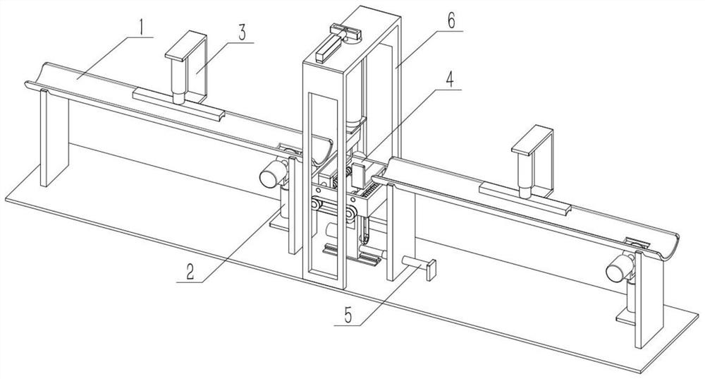
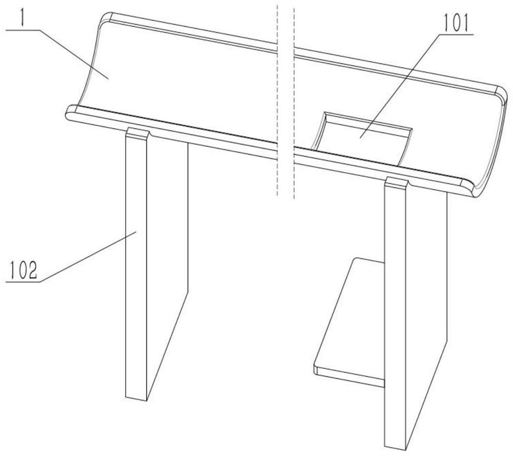
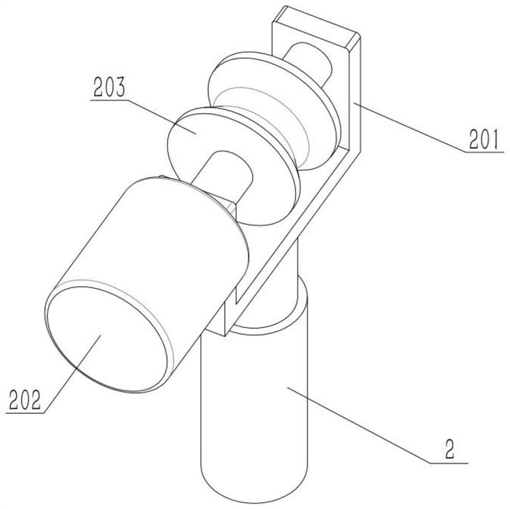
[0030] As shown in the figure, a building reinforcement cutting device includes an auxiliary mechanism, the auxiliary mechanism includes a half-arc guide bracket 1, a passage port 101, a support plate 102, an electric push rod 2, a half-wrapped seat 201, a motor I 202 and a guide wheel 203, the right side of the half-arc guide bracket 1 is provided with a passage opening 101, the left and right sides of the lower end of the half-arc guide bracket 1 are fixedly connected to the support plate 102, and the movable end of the electric push rod 2 is fixedly connected to the half-wrapped seat 201, and the half-wrapped seat 201 The rear end of the motor I202 is fixedly connected, and the output shaft of the motor I202 is connected to the front and rear ends of the half-pack seat 201. The guide wheel 203 is fixedly connected to the middle of the output shaft of the motor I202. The guide wheel 203 is located directly below the passage port 101. The push rod 2 is fixedly connected to the...

specific Embodiment approach 2

[0033] As shown in the figure, the auxiliary mechanism also includes a mounting frame 3, an electric push rod II 301 and a bead 302. The front end of the half-arc guide bracket 1 is fixed to the mounting frame 3, and the upper end of the mounting frame 3 is fixed to the electric push rod II 301. The movable end of the electric push rod II 301 is fixedly connected to the bead 302, which is located directly above the semi-arc guide bracket 1, and the lower end of the bead 302 is provided with a bar-shaped arc. When cutting the steel bar, it is necessary to fix the steel bar, start the electric push rod II 301, the electric push rod II 301 drives the bead 302 to descend, and utilize the bead 302 to hold the steel bar on the semi-arc guide bracket 1, so that the steel bar cannot move.

specific Embodiment approach 3

[0035] As shown in the figure, there are two auxiliary mechanisms in a linear array, and the distance between the inner end surfaces of the two semi-arc guide brackets 1 is 10 to 30 cm.

[0036] Place the left and right sides of the steel bars on the two semi-arc guide brackets 1 correspondingly, and then after the cross-cutting position is suspended, the left and right sides of the cutting-off position are supported and fixed, so that the steel bars will not be cut when the cutting force is applied to the cutting-off position. Lifting or movement occurs to ensure the cutting quality. The truncated right end utilizes the guide wheel 203 located on the right side to convey this section of steel bar away, thereby facilitating the formation of an assembly line.


PUM


Abstract

The invention relates to a cut-off device, in particular to a building reinforcing steel bar cut-off device. The building reinforcing steel bar cut-off device comprises an auxiliary mechanism, whereinthe auxiliary mechanism comprises a semi-arc guide support, a through hole, supporting plates, an electric push rod, a semi-packed seat, a motor I and a guide wheel, wherein the through hole is formed in the right side of the semi-arc guide support; the supporting plates are fixedly connected to left and right sides of the lower end of the semi-arc guide support; the movable end of the electric push rod is fixedly connected to the semi-packed seat; the rear end of the semi-packed seat is fixedly connected to the motor I; the output shaft of the motor I is rotatably connected to front and rearends of the semi-packed seat; the guide wheel is fixedly connected to the middle part of the output shaft of the motor I; the guide wheel is positioned below the through hole; and the electric push rod is fixedly connected to the supporting plate at the right side. The guide wheel can drive a reinforcing steel bar to separate from the semi-arc guide block to realize horizontal motion for reducingfriction force during movement. The guide wheel can drive the reinforcing steel bar to slightly separate from the semi-arc guide support to realize horizontal motion for reducing friction force during movement.

Description

technical field [0001] The invention relates to a cutting device, in particular to a construction steel bar cutting device. Background technique [0002] For example, the publication number is CN210188333U, a kind of steel bar cutting machine truncated steel bar auxiliary device, comprising a steel bar cutting machine, the bottom of the steel bar cutting machine is provided with a frame, and one side of the steel bar cutting machine is provided with a steel bar frame, and the steel bar is cut The top of the cutting machine is provided with a switch handle of the cutting machine, and the outer side of the switch handle of the cutting machine is provided with a collar one, and one side of the collar one is fixedly connected with a linkage steel wire, and the side of the steel bar frame far away from the end of the steel bar cutting machine passes through The bolts are fixedly connected with a steel wire fixing frame, and the outer side of the steel wire fixing frame is provide...

Claims


Application Information

Patent Timeline
Patent Type & Authority Applications(China)
IPC IPC(8): B21F11/00
CPCB21F11/00
Inventor 孙清梅王梦飞
Owner ZHEJIANG GUANGSHA COLLEGE OF APPLIED CONSTRTECH
Why Eureka
Try Eureka