Barrel beehive chamfering equipment for animal husbandry

A technology for animal husbandry and beehives, which is applied in the field of beehive chamfering equipment for animal husbandry. It can solve the problems of speeding up the chamfering efficiency, uneven corners poured from the inner wall of the beehive barrel, and large energy consumption, so as to improve the chamfering efficiency. Angular efficiency, effect of shortening placement time

Pending Publication Date: 2021-03-12
李龙
View PDF0 Cites 1 Cited by
  • Summary
  • Abstract
  • Description
  • Claims
  • Application Information

AI Technical Summary

Problems solved by technology

[0004] In order to overcome the manual chamfering of workers, it takes a lot of effort. At the same time, the strength of workers swinging the tool is different each time, which will cause the corners poured out of the inner wall of the drum beehive to be uneven, and the workers also need to manually chamfer the drum beehive. The shortcoming of fixed chamfering efficiency is low. The purpose of the present invention is to provide a kind of beehive chamfering work that can be completed without the need for workers to expend a lot of effort. Barrel beehive chamfering equipment for animal husbandry that speeds up the chamfering efficiency by fixing the barrel beehive

Method used


Image

  • Barrel beehive chamfering equipment for animal husbandry
  • Barrel beehive chamfering equipment for animal husbandry
  • Barrel beehive chamfering equipment for animal husbandry

Examples


Embodiment 1

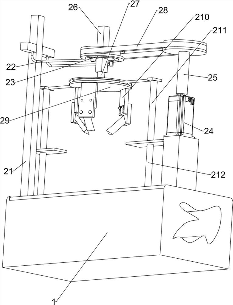
[0064] A drum beehive chamfering equipment for animal husbandry, such as figure 1 As shown, it includes a base plate 1 , a cutting mechanism 2 and a clamping and positioning mechanism 3 , the cutting mechanism 2 is provided on the top of the base plate 1 , and the clamping and positioning mechanism 3 is installed on the top of the base plate 1 .

[0065] When the worker needs to chamfer the drum beehive, the worker first needs to place the drum beehive in the middle of the top of the bottom plate 1, the drum beehive will push the clamping positioning mechanism 3 to move outward, and the clamping positioning mechanism 3 will reset. The clamping and positioning mechanism 3 will clamp and fix the drum beehive, and then the worker starts the cutting mechanism 2 to rotate, and then manually presses the cutting mechanism 2 downwards, and the cutting mechanism 2 moves downward to chamfer the drum beehive. After the mechanism 2 completes the chamfering work of the drum beehive, the wo...

Embodiment 2

[0067] In a preferred embodiment of the present invention, as figure 2 As shown, the cutting mechanism 2 includes a first support frame 21, a connecting rod 22, a support arc block assembly 23, a first motor 24, a first rotating shaft 25, a rotating block 26, a second rotating shaft 27, a first transmission assembly 28, and a turntable 29. Cutter assembly 210, support assembly 211 and first extension rod 212. A first support frame 21 is provided on the middle right side of the top of the bottom plate 1. The upper part of the first support frame 21 is symmetrically provided with a connecting rod 22. The inner end of the connecting rod 22 rotates at the top There is a supporting arc block assembly 23, the left side of the top of the bottom plate 1 is connected with a first motor 24 by bolts, the output shaft of the first motor 24 is connected with a first rotating shaft 25, and the sliding type in the middle of the supporting arc block assembly 23 is provided with a rotating sha...

Embodiment 3

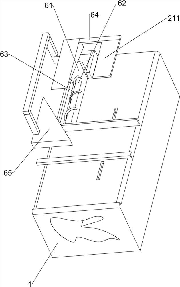
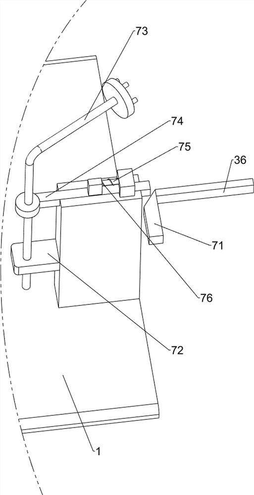
[0070] In a preferred embodiment of the present invention, as figure 1 , image 3 , Figure 4 , Figure 5 , Figure 6 and Figure 7 As shown, the clamping positioning mechanism 3 includes a first wedge fast 31, a second telescopic rod 32, a clamp block assembly 33, a first spring 34, a third telescopic rod 35, a first baffle plate 36 and a second spring 37, both The inner side of the bottom end of the first extension rod 212 is fixedly connected with the first wedge-shaped fastening 31, and the middle of the top of the bottom plate 1 is symmetrically provided with the second telescopic rod 32, and the outer end of the second telescopic rod 32 is slidably provided with a clamping block assembly 33. The two telescopic rods 32 are equipped with a first spring 34, and the two ends of the first spring 34 are connected to the clamping block assembly 33 and the second telescopic rod 32 respectively, and the outside of the clamping block assembly 33 is provided with a third telesc...


PUM


Abstract

The invention relates to chamfering equipment, in particular to barrel beehive chamfering equipment for animal husbandry. The barrel beehive chamfering equipment for animal husbandry can complete barrel beehive chamfering work without consuming large strength by workers, and meanwhile, can ensure that the chamfering strength of each time is the same, and can also fix a barrel beehive, so that thechamfering efficiency is improved. The barrel beehive chamfering equipment for animal husbandry comprises a bottom plate and a cutting mechanism, wherein the cutting mechanism is arranged at the top of the bottom plate. According to the barrel beehive chamfering equipment for animal husbandry, the cutting mechanism is arranged, the cutting mechanism is matched with a clamping and positioning mechanism, so that chamfering and clamping and positioning work of the barrel beehive can be realized; a pressing mechanism is arranged, so that a rotating block does not need to be manually pressed downwards by workers, and the chamfering efficiency of the barrel beehive is further improved; and a feeding and discharging mechanism is matched with a pushing mechanism, so that the work of automaticallypushing the barrel beehive to a designated position at intervals can be realized, and the placing time of the barrel beehive is effectively shortened.

Description

technical field [0001] The invention relates to chamfering equipment, in particular to a chamfering equipment for drum beehives used in animal husbandry. Background technique [0002] The beehive is the most basic and essential beekeeping tool. The drum beehive is the earliest and most widely used traditional beehive in my country. Especially before the introduction of the live frame beehive, my country basically used the drum beehive to raise the middle bees. According to the nesting habits of the bees and the characteristics of the hive, the beehive is designed in a barrel shape. At the same time, the ventilation inside the beehive and the airtightness outside the beehive must be ensured. In addition, heat preservation, waterproof and insect resistance are also important indicators for designing a barrel beehive. In order to ensure the flatness of the inner wall of the barrel beehive during the production process of the barrel beehive, the workers generally use knives to cha...

Claims


Application Information

Patent Timeline
Patent Type & Authority Applications(China)
IPC IPC(8): B23B5/00B23Q3/06B23Q5/28B23Q5/34
CPCB23B5/00B23Q3/06B23Q5/28B23Q5/34
Inventor 李龙
Owner 李龙
Why Eureka
Try Eureka