Workpiece rotating platform for machining
A technology of mechanical processing and rotary table, which is applied in the direction of metal processing machinery parts, metal processing equipment, manufacturing tools, etc., can solve the problems of inability to guarantee processing accuracy, inconvenient operation, low efficiency, etc., and achieve convenient control and time-consuming position adjustment Short, easy-to-use effect
- Summary
- Abstract
- Description
- Claims
- Application Information
AI Technical Summary
Problems solved by technology
Method used
Image
Examples
Embodiment 1
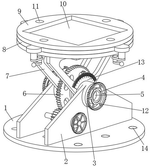
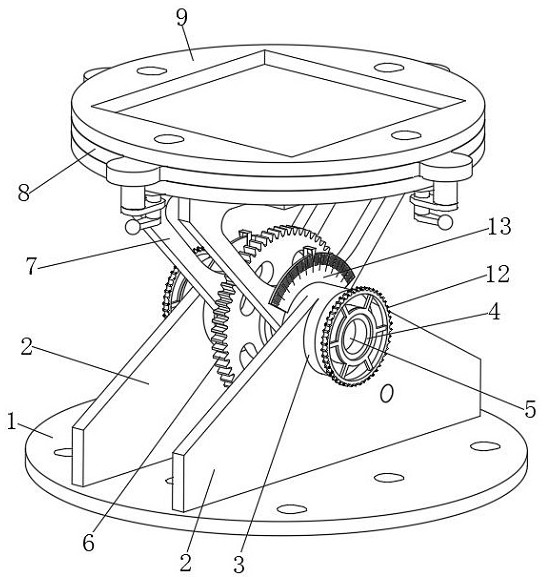
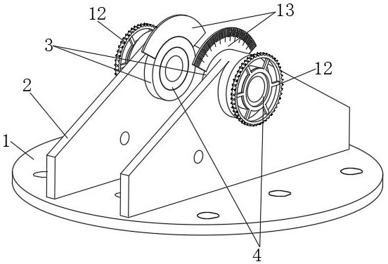
[0031] A workpiece rotary table for mechanical processing, such as Figure 1-3 As shown, including the mounting plate 1, the upper middle front part and the upper middle rear part of the mounting plate 1 are fixedly connected with the support plate 2, and the two support plates 2 are triangular structures, and the upper parts of the two support plates 2 are inserted and fixedly connected. There is a support tube 3, and the two support tubes 3 are movable connected with an elastic tube 4, and the two elastic tubes 4 are interspersed with a rotating shaft 5, and the middle part of the outer surface of the rotating shaft 5 is interspersed and fixedly connected with a flip adjustment mechanism 6 and a support Mechanism 7, the overturn adjustment mechanism 6 is arranged in the support mechanism 7, the support mechanism 7 is movably connected between the two support cylinders 3, the inner surfaces of the two elastic cylinders 4 are respectively movably connected with the front and re...
Embodiment 2
[0035] On the basis of Example 1, as Figure 4-5 As shown, a workpiece rotary table for mechanical processing includes a mounting plate 1, and the upper middle front part and the upper middle rear part of the mounting plate 1 are fixedly connected with a support plate 2, and the two support plates 2 are triangular structures. The upper part of the support plate 2 is interspersed and fixedly connected with a support tube 3, and the two support tubes 3 are movably connected with an elastic tube 4, and the two elastic tubes 4 are jointly interspersed with a rotating shaft 5, and the middle part of the outer surface of the rotating shaft 5 is interspersed. Fixedly connected with an overturn adjustment mechanism 6 and a support mechanism 7, the overturn adjustment mechanism 6 is arranged in the support mechanism 7, the support mechanism 7 is movably connected between the two support cylinders 3, and the inner sides of the two elastic cylinders 4 are respectively connected to the fro...
Embodiment 3
[0040] On the basis of Example 1, as Figure 6-7 As shown, a workpiece rotary table for mechanical processing includes a mounting plate 1, and the upper middle front part and the upper middle rear part of the mounting plate 1 are fixedly connected with a support plate 2, and the two support plates 2 are triangular structures. The upper part of the support plate 2 is interspersed and fixedly connected with a support tube 3, and the two support tubes 3 are movably connected with an elastic tube 4, and the two elastic tubes 4 are jointly interspersed with a rotating shaft 5, and the middle part of the outer surface of the rotating shaft 5 is interspersed. Fixedly connected with an overturn adjustment mechanism 6 and a support mechanism 7, the overturn adjustment mechanism 6 is arranged in the support mechanism 7, the support mechanism 7 is movably connected between the two support cylinders 3, and the inner sides of the two elastic cylinders 4 are respectively connected to the fro...
PUM
 Abstract
Description
Claims
Application Information
 - R&D
- Intellectual Property
- Life Sciences
- Materials
- Tech Scout
- Unparalleled Data Quality
- Higher Quality Content
- 60% Fewer Hallucinations
Browse by: Latest US Patents, China's latest patents, Technical Efficacy Thesaurus, Application Domain, Technology Topic, Popular Technical Reports.
© 2025 PatSnap. All rights reserved.Legal|Privacy policy|Modern Slavery Act Transparency Statement|Sitemap|About US| Contact US: help@patsnap.com


