CNC machine tool for impeller end gear shaft machining

A technology of end teeth and impellers, which is applied in the direction of metal processing machinery parts, metal processing equipment, manufacturing tools, etc., can solve the problems of glass blocking, inconvenient glass cleaning, cutting fluid splashing, etc., to achieve easy installation and disassembly, and easy replacement of activities Clean-up, easy-to-clean effect

Inactive Publication Date: 2021-03-12
雄名航空科工(芜湖)股份有限公司
View PDF9 Cites 0 Cited by
  • Summary
  • Abstract
  • Description
  • Claims
  • Application Information

AI Technical Summary

Problems solved by technology

[0003] When the CNC lathe is processing the gear shaft at the impeller end, it needs to use cutting fluid to spray the cutting part. Therefore, if the cutting head is changing the angle and moving, the cutting fluid will be sprayed on the cutting head, which will easily lead to cutting. The splash of the cutting fluid, accompanied by debris, so that the cutting fluid and debris are easy to splash on the glass on the sliding door of the CNC machine tool. Due to the accumulation of cutting fluid and debris, it is not convenient for the staff to clean the glass, which is easy to cause glass damage. Some will use a towel to wipe the glass, but the debris is easy to hurt the hands of the staff, which will affect the observation of the processing of the gear shaft at the impeller end, and there are certain limitations

Method used


Image

  • CNC machine tool for impeller end gear shaft machining
  • CNC machine tool for impeller end gear shaft machining
  • CNC machine tool for impeller end gear shaft machining

Examples


Embodiment Construction

[0024] The following will clearly and completely describe the technical solutions in the embodiments of the present invention with reference to the accompanying drawings in the embodiments of the present invention. Obviously, the described embodiments are only some, not all, embodiments of the present invention. Based on the embodiments of the present invention, all other embodiments obtained by persons of ordinary skill in the art without making creative efforts belong to the protection scope of the present invention.

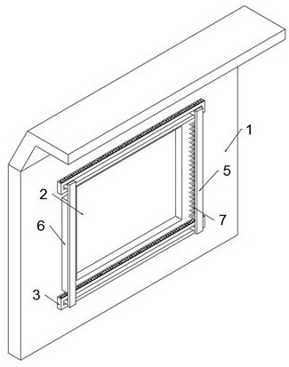
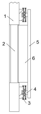
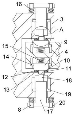
[0025] The present invention provides such Figure 1-6 The CNC machine tool shown for machining the gear shaft at the impeller end includes a sliding door 1, a glass 2 is arranged in the middle of the sliding door 1, and a mounting plate 3 is symmetrically fixedly connected to one side of the sliding door 1, and the mounting plate 3 is beneficial to the sliding block. 4 for installation and disassembly, which facilitates the sliding of the sliding block 4 on i...


PUM


Abstract

The invention discloses a CNC machine tool for impeller end gear shaft machining. The CNC machine tool comprises a sliding door, wherein glass is arranged in the middle portion of the sliding door; amounting plate is fixedly connected to one side of the sliding door, two sliding plates are arranged on one side of the mounting plate, sliding blocks are fixedly connected to the tops and the bottomsof one sides of the sliding plates, and a sliding groove is formed in one side of the mounting plate; one side of one of the sliding plates is fixedly connected with a sponge block, and a plurality of bristles are arranged in the other side of the other sliding plate in an embedded mode; and grooves are formed in the tops and the bottoms of the sliding blocks, guide blocks are arranged in inner cavities of the grooves, and fixing blocks are fixedly connected to the edge sides of the guide blocks. According to the CNC machine tool for impeller end gear shaft machining, by means of mutual cooperation of the mounting plate, the sliding blocks, the sliding plates, the sponge block and the bristles, the glass can be cleaned conveniently, so that cutting fluid and chippings can be cleared awayfrom the glass conveniently, the machining condition of an impeller end gear shaft can be observed conveniently through the glass, and meanwhile, the mounting plate can be arranged and disarranged conveniently.

Description

technical field [0001] The invention relates to the field of CNC machine tools, in particular to a CNC machine tool for processing the gear shaft at the end of the impeller. Background technique [0002] The gear shaft at the impeller end needs to use CNC machine tools. CNC machine tools are also called numerical control machine tools. CNC machine tools are short for digital control machine tools. They are automatic machine tools equipped with program control systems. Process the program specified by the control code or other symbolic instructions, decode it, express it in coded numbers, input it into the numerical control device through the information carrier, and send various control signals from the numerical control device after calculation processing to control the movement of the machine tool. The shape and size required by the drawings can automatically process the parts. The CNC machine tool solves the problem of complex, precise, small batch and multi-variety parts...

Claims


Application Information

Patent Timeline
Patent Type & Authority Applications(China)
IPC IPC(8): B23Q11/00B23Q11/08
CPCB23Q11/0042B23Q11/08
Inventor 王培勇石得林
Owner 雄名航空科工(芜湖)股份有限公司
Why Eureka
Try Eureka