Rounded corner structure and rounded corner forming method
A technology of rounded corner forming and rounded corners, which is applied in the field of rounded corner structure and rounded corner forming, can solve the problems of not being able to meet the requirements of rounded corner chamfering in appearance design, and achieve the effect of strengthening strength and high processing precision
- Summary
- Abstract
- Description
- Claims
- Application Information
AI Technical Summary
Problems solved by technology
Method used
Image
Examples
Embodiment 1
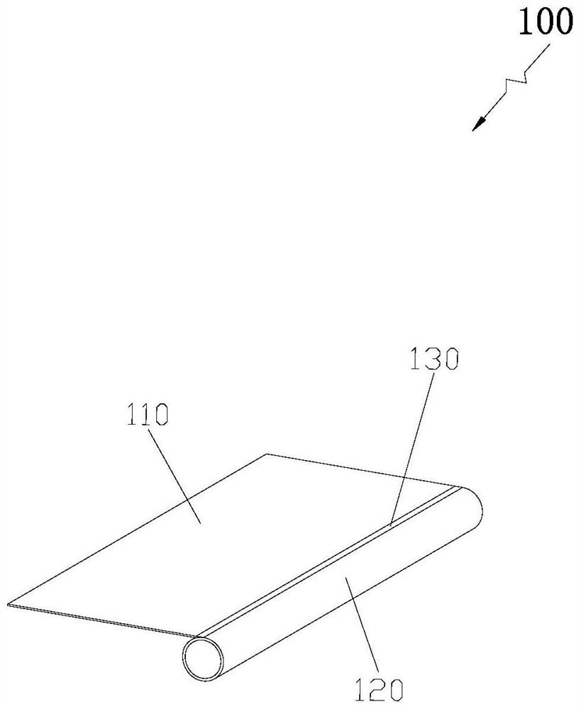
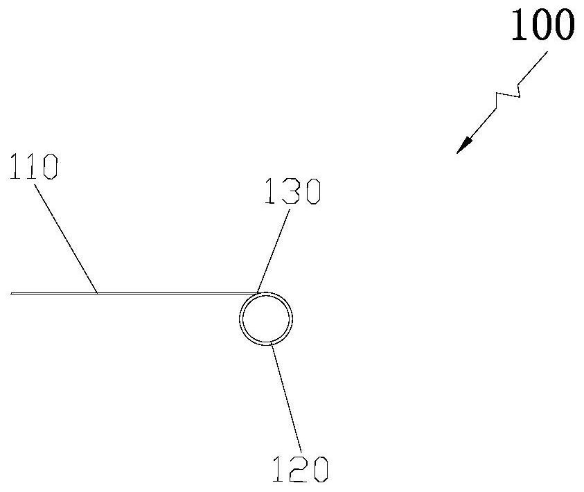
[0022] Such as figure 1 and figure 2 As shown, Embodiment 1 of the present invention provides a rounded corner structure 100. The rounded corner structure 100 includes a first plate 110 and a round tube 120. The side of the first plate 110 parallel to the extending direction of the round tube 120 passes through the first The smooth welding surface 130 is disposed in contact with the outer side of the round tube 120 to form a rounded corner structure on one side of the first plate 110 .
[0023] In this example, if figure 1 and figure 2 As shown, the above-mentioned first plate 110 can be cut into any shape according to actual needs, it only needs to ensure that the length of the side of the first plate 110 parallel to the extension direction of the round tube 120 is the same as the length of the round tube 120. A plate 110 is preferably a metal plate, and similarly, the round pipe 120 is also preferably a metal round pipe, so that the two can be smoothly transitioned thro...
Embodiment 2
[0026] Such as Figure 4 As shown, Embodiment 2 of the present invention provides a fillet forming method, which specifically includes the following steps:
[0027] Step S110: providing a first plate and a round tube, respectively fixing the first plate and the round tube at preset positions, and making the side of the first plate and the round tube parallel to the extending direction abut against the outer side of the round tube, And the plane where the first plate is located is set tangent to the outer side of the circular tube.
[0028] Specifically, such as Figure 5 As shown, the first plate 110 and the round pipe 120 are respectively fixed by using the fixing fixture 200 through a two-point fixing method (that is, the two fixing fixtures 200 are separated by a preset distance one after the other), so that the first plate 110 and the round pipe are respectively fixed. 120 is fixed at a preset position, and the side of the first plate 110 parallel to the extension direct...
Embodiment 3
[0036] Such as Figure 5 As shown, Embodiment 3 of the present invention provides a fillet forming method, which specifically includes the following steps:
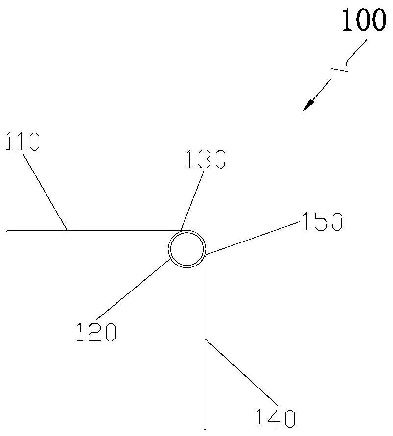
[0037] Step S210: providing a first plate, a second plate and a round tube, respectively fixing the first plate, the second plate and the round tube at preset positions, and making the first plate and the extending direction of the round tube parallel to each other One side, the second plate and the side parallel to the extension direction of the round tube respectively abut against the outer side of the round tube, and the plane where the first plate is located and the plane where the second plate is located are respectively arranged tangentially to the outer side of the round tube, the first plate The plane where it is located and the plane where the second plate is located are set at a preset angle.
[0038] Step S220: Perform spot welding operations between one side of the first plate and the outside of the round pip...
PUM
 Abstract
Description
Claims
Application Information
 - R&D
- Intellectual Property
- Life Sciences
- Materials
- Tech Scout
- Unparalleled Data Quality
- Higher Quality Content
- 60% Fewer Hallucinations
Browse by: Latest US Patents, China's latest patents, Technical Efficacy Thesaurus, Application Domain, Technology Topic, Popular Technical Reports.
© 2025 PatSnap. All rights reserved.Legal|Privacy policy|Modern Slavery Act Transparency Statement|Sitemap|About US| Contact US: help@patsnap.com


