
Special tool for chamfers on front and back sides of connecting holes at flange ends of camshaft

A technology for connecting holes and camshafts, which is applied in the field of metal cutting and cutting processing. It can solve the problems that the processing quality cannot meet the drawing requirements, cannot use drill bits for processing, and the processing efficiency is low, so as to improve the processing quality and processing efficiency. Simple, easy-to-operate effects

Active Publication Date: 2014-12-17
CSSC MARINE POWER
View PDF6 Cites 0 Cited by
  • Summary
  • Abstract
  • Description
  • Claims
  • Application Information

AI Technical Summary

Problems solved by technology

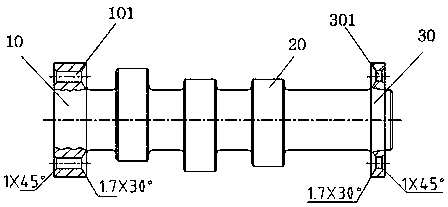
like figure 1 As shown, the camshaft structure is flanges at both ends, and the long axis of several cams 20 with different starting angles is arranged in the middle, and the first end flange 10 and the second end flange 30 of the camshaft are evenly distributed in multiple radial directions. The first end flange connection hole 101, the plurality of second end flange connection holes 301, the front and back sides of the plurality of first end flange connection holes 101 and the plurality of second end flange connection holes 301 respectively need to be chamfered 1×45° and 1.7×30°, the 1×45° chamfer on the front side of each connection hole can be processed by a specially ground drill bit, and the 1.7×30° chamfer on the back side of each connection hole cannot be processed by a drill bit, only Manual grinding process, inconvenient operation, low processing efficiency, processing quality can not meet the drawing requirements

Method used


Image

  • Special tool for chamfers on front and back sides of connecting holes at flange ends of camshaft
  • Special tool for chamfers on front and back sides of connecting holes at flange ends of camshaft
  • Special tool for chamfers on front and back sides of connecting holes at flange ends of camshaft

Examples


Embodiment Construction

[0016] Below in conjunction with accompanying drawing and embodiment the present invention will be further described:

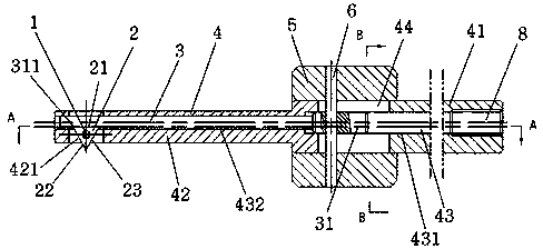
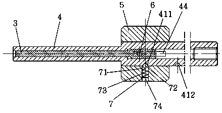
[0017] like Figure 2 ~ Figure 4 As shown, it includes a chamfering blade support shaft 1, a chamfering blade 2, a push rod 3, a handle 4, a control sleeve 5, a horizontal pin 6 and a movement limit mechanism 7 of the control sleeve. The handle 4 is a stepped shaft structure, and the control sleeve 5 is sleeved on the large end shaft 41 of the handle of a knife 4, and both clearance fits. Axial stepped through hole 43 is provided in the handle of a knife 4, and the middle part of the large end shaft 41 of the handle of a knife 4 is provided with the middle part transverse channel 44 orthogonal to the large end hole 431 of the stepped through hole 43 of the axial direction. The end of the end shaft 42 is provided with a blade transverse through groove 421 orthogonal to the small end hole 432 of the axially stepped through hole 43 . The chamfering blade 2 is ...


PUM


Abstract

The invention discloses a special tool for chamfering front and back sides of a connecting hole at flange ends of a camshaft. The special tool comprises a chamfering blade support shaft, a chamfering blade, a push rod, a tool handle, a control sleeve, a horizontal pin and a control sleeve movement spacing mechanism, wherein the control sleeve is sheathed on the tool handle, the middle part of the large end shaft of the tool handle is provided with a middle horizontal slot, and the small end shaft of the tool handle is provided with a horizontal blade slot; the chamfering blade is embedded in one side of the horizontal blade slot, and the push rod is in a stepped shaft structure, and is sheathed in a vertical step through hole; and a horizontal pin penetrates the control sleeve, the middle horizontal slot of the tool handle and the large end shaft of the push rod, and the control sleeve movement spacing mechanism is arranged on a connecting surface of the tool handle and the control sleeve. The special tool disclosed by the invention has the advantages of simple and compact structure, convenience in operation, and low cost of design and manufacturing. The special tool can be used for chamfering front and back sides of the connecting hole at the flange ends of the camshaft, and can solve the problem that in the prior art the tool can not be used for chamfering the connecting hole at the back side of the flange end of the camshaft. Moreover, the special tool can enhance the processing quality and the processing efficiency.

Description

technical field [0001] The invention relates to the cutting processing of shaft parts with flanges at both ends, in particular to a special tool for chamfering the front and back faces of multiple connection holes on the flanges at both ends of the diesel engine camshaft, which belongs to the metal cutting processing technology field. Background technique [0002] The camshaft is one of the important parts of the diesel engine. Its function is to accurately control the opening and closing of the valve according to a certain time through the transmission parts (rocker arm, timing chain, sprocket), so as to ensure that the engine is ventilated according to a certain rule. like figure 1 As shown, the camshaft structure is flanges at both ends, and the long axis of several cams 20 with different starting angles is arranged in the middle, and the first end flange 10 and the second end flange 30 of the camshaft are evenly distributed in multiple radial directions. The first end ...

Claims


Application Information

Patent Timeline
Patent Type & Authority Patents(China)
IPC IPC(8): B23B27/00
Inventor 汤忠良汪培宏王敬洪黄汉龙陈广平廖新山
Owner CSSC MARINE POWER
Learn More