Wide belt sander micro-airflow abrasive belt position detection device and control method

A wide-band sander and detection device technology, which is applied in the direction of abrasive belt grinder, workpiece feed movement control, manufacturing tools, etc., can solve the problems of poor health impact, slow reaction process, and large noise, and achieve equipment saving Expenditure on Internet, rapid response, and less equipment expenditure

Pending Publication Date: 2021-03-12
湖北永吉智能家居有限公司
View PDF8 Cites 0 Cited by
  • Summary
  • Abstract
  • Description
  • Claims
  • Application Information

AI Technical Summary

Problems solved by technology

Its disadvantages: the photoelectric switch is used to detect the position of the abrasive belt, and the output signal is sent to the control mechanism to realize the function. Since the sander is a high-efficiency grinding method, a large amount of abrasive debris is generated, and the internal environment of the machine is very poor. The photoelectric switch requires a relatively high detection environment, so abnormal shutdowns due to lens pollution often occur, seriously affe...

Method used


Image

  • Wide belt sander micro-airflow abrasive belt position detection device and control method
  • Wide belt sander micro-airflow abrasive belt position detection device and control method
  • Wide belt sander micro-airflow abrasive belt position detection device and control method

Examples


Embodiment Construction

[0025] The following will clearly and completely describe the technical solutions in the embodiments of the present invention with reference to the accompanying drawings in the embodiments of the present invention. Obviously, the described embodiments are only some, not all, embodiments of the present invention. Based on the embodiments of the present invention, all other embodiments obtained by persons of ordinary skill in the art without making creative efforts belong to the protection scope of the present invention.

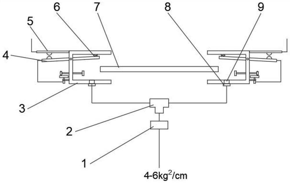
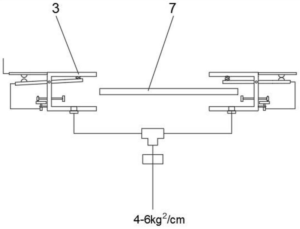
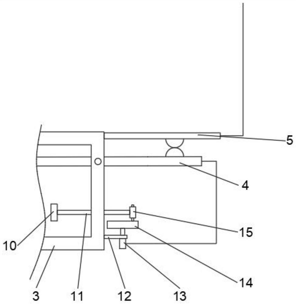
[0026] see Figure 1~4 , in the embodiment of the present invention, the micro-airflow abrasive belt position detection device of a broadband sander includes an abrasive belt 7 and an air-controlled insert 3 arranged on both sides of the abrasive belt 7 and symmetrical to the abrasive belt 7. The air-controlled insert 3 is The opening faces the C-shaped insert of the abrasive belt 7, and the abrasive belt 7 is located in the opening of the air control insert 3...


PUM


Abstract

The invention discloses a wide belt sander micro-airflow abrasive belt position detection device and a control method, and relates to the field of belt sander abrasive belt control mechanism manufacturing. The wide belt sander micro-airflow abrasive belt position detection device specifically comprises an abrasive belt and pneumatic control inserting plates arranged on the two sides of the abrasive belt and symmetrical about the abrasive belt, wherein blowing holes are formed in the bottoms of the pneumatic control inserting plates, connecting caps are arranged at the bottoms of the blowing holes, the connecting caps at the bottoms of the pneumatic control inserting plates on the two sides of the abrasive belt are fixedly connected with ports in the two sides of a same three-way pipe through pipelines correspondingly, a port in the middle of the three-way pipe is fixedly connected with the output end of an air blowing pressure regulating valve, and compressed air is introduced into theinput end of the air blowing pressure regulating valve. Compared with a detection device in the prior art, in the technical scheme, deviation rectification of the abrasive belt is controlled throughon-off of a circuit, only a stepping motor needs to work autonomously in the whole deviation rectification work, the reaction speed is higher, expenditure on equipment is saved, and the beneficial effects of being lower in noise, faster in reaction and less in equipment expenditure are achieved.

Description

technical field [0001] The invention relates to the field of manufacturing the abrasive belt control mechanism of a belt sander, in particular to a detection device and a control method for the micro-airflow abrasive belt position of a wide-band sander. Background technique [0002] CN102814716A, titled "An automatic deviation correction mechanism for abrasive belts of polishing machines", including infrared sensors, DC servo motors, eccentric wheels, connecting rods, worm gear transmission mechanisms and deviation correction rollers; the infrared sensor, DC servo motor and worm gear transmission The mechanisms are all fixed on the bottom plate of the polishing machine; the deviation correcting roller is coaxially sleeved on the worm of the worm gear and worm transmission mechanism, and connected by a bearing, so that the deviation correction roller can rotate freely on the worm; the infrared sensor detects the running of the abrasive belt of the polishing machine. deviation...

Claims


Application Information

Patent Timeline
IPC IPC(8): B24B21/20B24B49/00
CPCB24B21/20B24B49/00
Inventor 游永青
Owner 湖北永吉智能家居有限公司
Why Eureka
Try Eureka