
Manipulator tool clamping mechanism

A clamping mechanism and manipulator technology, applied in the field of manipulators, can solve problems such as low fault tolerance rate, tool drop, tool damage, etc., to achieve the effect of increasing fault tolerance rate, preventing tool drop, and avoiding damage to tools

Pending Publication Date: 2021-03-12
宁波凯理特机器人科技有限公司
View PDF0 Cites 0 Cited by
  • Summary
  • Abstract
  • Description
  • Claims
  • Application Information

AI Technical Summary

Problems solved by technology

[0004] However, during the working process of the existing pneumatic gripper, if the cylinder loses air, the tool will fall, which may cause damage to the tool; at the same time, the existing pneumatic gripper allows less error when grabbing the tool, and the fault tolerance rate not tall

Method used


Image

  • Manipulator tool clamping mechanism
  • Manipulator tool clamping mechanism
  • Manipulator tool clamping mechanism

Examples

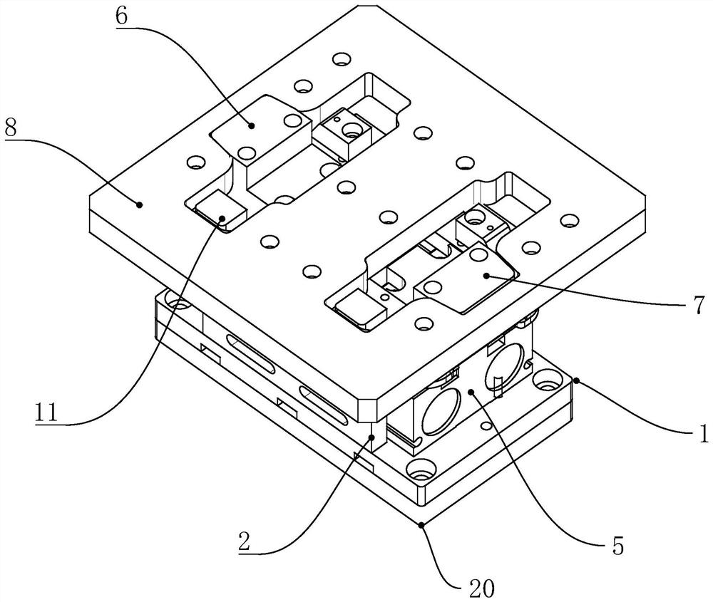
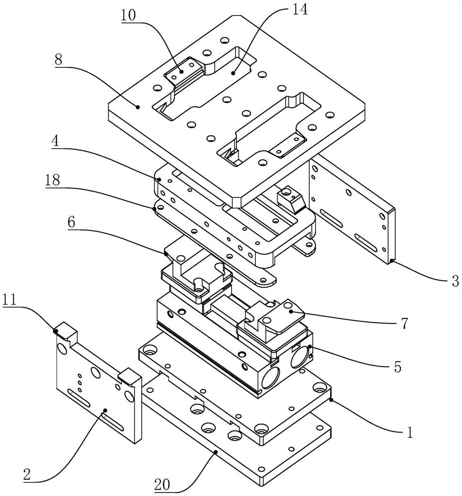
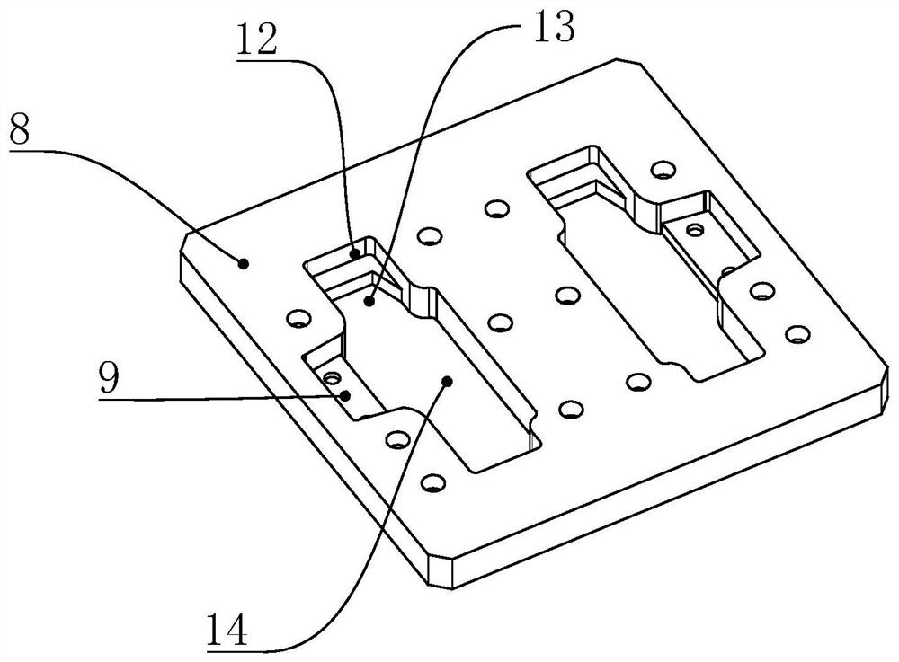

Embodiment Construction

[0025] The present invention will be further described below in conjunction with specific examples, but the present invention is not limited to these specific embodiments. Those skilled in the art will realize that the present invention covers all alternatives, modifications and equivalents as may be included within the scope of the claims.

[0026] Such as Figure 1-5 As shown, the manipulator tool clamping mechanism is shown, including a fixed seat 1, a hook plate 2, a first fixed block 3, a second fixed block 4, a clamping cylinder 5, a first clamping block 6, a second clamping block 7 and tools plate 8, the hook plate 2 and the first fixing block 3 are arranged on both sides of the fixing seat 1, and the second fixing block 4 is arranged between the hook plate 2 and the first fixing block 3 Between, the clamping cylinder 5 is arranged between the fixing base 1 and the second fixing block 4, the first clamping block 6 and the second clamping block 7 are connected to the cl...


PUM


Abstract

The invention relates to a manipulator tool clamping mechanism which comprises a fixing seat, a hook plate, a first fixing block, a second fixing block, a clamping air cylinder, a first clamping block, a second clamping block and a tool plate, the hook plate and the first fixing block are arranged on the two sides of the fixing seat, and the second fixing block is arranged between the hook plate and the first fixing block. The clamping air cylinder is arranged between the fixing seat and the second fixing block, the first clamping block and the second clamping block are connected to an outputend of the clamping air cylinder, the first clamping block and the second clamping block are in sliding fit with the second fixing block, two first concave parts corresponding to the first clamping block and the second clamping block are arranged on the two sides of the tool plate, and gaskets are arranged in the first concave parts. The upper surfaces of the gaskets are inclined, and the first clamping block and the second clamping block are matched with the inclined surfaces. According to the designed manipulator tool clamping mechanism, the error-tolerant rate is high when a manipulator grabs a tool, meanwhile, the tool clamping position is accurate, and the tool cannot fall off due to loss of an air cylinder in the working process.

Description

technical field [0001] The invention relates to the field of manipulators, in particular to a tool clamping mechanism of a manipulator. Background technique [0002] A manipulator is an automatic operating device that can imitate certain movement functions of the human hand and arm to grab, carry objects or operate tools according to a fixed program. [0003] The most commonly used structure of the manipulator is the gripper mechanism, which is used to grab square objects. Generally, it can be divided into pneumatic grippers and mechanical grippers. Pneumatic grippers are relatively simple, and can be realized directly by using a double-sided translational clamping cylinder. Clamp and loosen. [0004] However, during the working process of the existing pneumatic gripper, if the cylinder loses air, the tool will fall, which may cause damage to the tool; at the same time, the existing pneumatic gripper allows less error when grabbing the tool, and the fault tolerance rate no...

Claims


Application Information

Patent Timeline
Patent Type & Authority Applications(China)
IPC IPC(8): B25J15/08B25J15/02
CPCB25J15/0253B25J15/08
Inventor 毛培民
Owner 宁波凯理特机器人科技有限公司
Learn More