Supercharge Your Innovation With Domain-Expert AI Agents!

Adhesive tape pressing mechanism

A technology for pressing tapes and racks, which is applied in metal processing and other directions, and can solve problems such as warped tapes, insufficient vacuum suction force of suction nozzles, and affecting tape replacement efficiency, and achieve the effect of improving replacement efficiency

Inactive Publication Date: 2021-03-12
苏州德睿联自动化科技有限公司
View PDF0 Cites 0 Cited by
  • Summary
  • Abstract
  • Description
  • Claims
  • Application Information

AI Technical Summary

Problems solved by technology

[0003] However, there are certain problems in the tape pressing mechanism during the existing tape production;
[0004] 1. When the existing adhesive tape is used to produce and cut hard adhesive tape, because the adhesive tape itself has high viscosity and the material is relatively thick and hard, and the vacuum adsorption force of the suction nozzle is not enough, so after the tape is cut, there will be a tape outside the upper suction nozzle. The phenomenon that the lower nozzle tape falls off occurs;
[0005] 2. When the existing tape pressing mechanism replaces the tape, because the structure is relatively complicated, it needs professional operators to operate before it can be replaced, which makes it difficult to disassemble the tape replacement structure, thereby affecting the replacement efficiency of the tape. For this reason, Propose a pressing belt mechanism

Method used


Image

  • Adhesive tape pressing mechanism
  • Adhesive tape pressing mechanism
  • Adhesive tape pressing mechanism

Examples


Embodiment

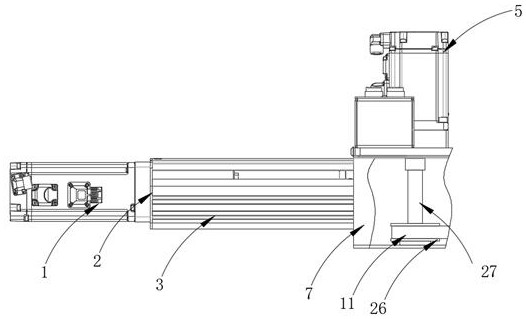
[0029] See Figure 1-5 The present invention provides a technical solution: a compact tape mechanism comprising a frame 7, a top surface of the frame 7 having a first plate body 6, a servo motor 5, servo motor 5, servo motor 5, servo motor 5 The output terminal penetrates the upper surface of the first plate body 6 and fixedly connected to the third rod 27, and the outer wall welded of the third rod 27 has a second rotary wheel 26, and one end of the bottom portion of the third rod 27 is rotated through the bearing to the rack. The bottom of the inner wall of the frame 7, the bottom of the frame 7 is rotated by the bearing, and the outer side wall of the first rotary wheel and the outer wall of the first rotary wheel and the outer wall of the second rotary wheel are transferred thereon, and the belt 11, the first The inner side wall of the runner 12 welded the roller 13, and the outer wall of the roller 13 is welded with a first turntable 14, and the upper surface of the first turn...


PUM


Abstract

The invention discloses an adhesive tape pressing mechanism. The adhesive tape pressing mechanism comprises a machine frame, a first plate body is welded to the top of the machine frame, a servo motoris arranged on the upper surface of the first plate body, and the output end of the servo motor penetrates through the upper surface of the first plate body and is fixedly connected with a third rodbody. According to the adhesive tape pressing mechanism, during use, the servo motor drives the third rod body and a second rotating wheel to rotate, the second rotating wheel drives a first rotatingwheel to rotate through a conveying belt, so that a rotating roller and a first rotating disc in the first rotating wheel rotate at the top of the machine frame, adhesive tape is wound around the first rotating disc and a suction nozzle, two compression rollers at the bottom of a third L-shaped plate press the surface of the adhesive tape all the time through acting force of a second sliding railand a second spring, so that a cutter can perform cutting conveniently, when the adhesive tape is replaced, a sliding block needs to be pushed, then the sliding block drives the third L-shaped plate and the compression rollers to leave the suction nozzle, at the moment, a butterfly bolt is rotated, one end of the butterfly bolt can penetrate through the sliding block and a second L-shaped plate, so that the spring is prevented from being reset, and then the adhesive tape is arranged on the surface of the suction nozzle.

Description

Technical field [0001] The present invention relates to the field of tape production, and in particular a compact tape mechanism. Background technique [0002] It is well known that the tape is composed of two parts of the substrate and adhesive, and the two or more non-connected objects are bonded together. A layer of adhesive is coated on the surface. The earliest adhesive is from animal and plants. In the nineteenth century, rubber is the main component of adhesives; modern polymers are widely used. The adhesive can stick to something because of the molecules of its own molecules and components to connect the articles, such a bonding can firmly bond the molecules. Ingredients of the adhesive, according to different manufacturers, different types, and various polymers. [0003] However, there is still a problem with the compact mechanism during the existing tape production; [0004] First, the existing tape is produced by cutting the hard tape, which is less hard due to the hig...

Claims


Application Information

Patent Timeline
IPC IPC(8): B26D7/02B26D7/08B26D7/00
CPCB26D7/00B26D7/015B26D7/025B26D7/08
Inventor 雷水德曾庆礼高宜江徐世亮张英男
Owner 苏州德睿联自动化科技有限公司
Features
  • R&D
  • Intellectual Property
  • Life Sciences
  • Materials
  • Tech Scout
  • Unparalleled Data Quality
  • Higher Quality Content
  • 60% Fewer Hallucinations
Learn More