High-speed digital printing machine

A printing machine and digital technology, which is applied in the field of high-speed digital printing machines, can solve problems such as troublesome operation, troublesome removal and installation of ink cartridges, and reduced printing efficiency of paper, so as to achieve the effect of good cutting and easy removal

Inactive Publication Date: 2021-03-12
浙江思印科技有限公司
View PDF4 Cites 0 Cited by
  • Summary
  • Abstract
  • Description
  • Claims
  • Application Information

AI Technical Summary

Problems solved by technology

[0004] The purpose of the present invention is: in order to solve the functional defects of existing digital printing machines, when printing paper, some large papers need to be cut by workers before they can be put into the printing machine for printing, but workers use tools to cut paper It is very troublesome. It needs to be cut on the cutting equipment and then transferred to the printing machine for printing. The troublesome operation is not conducive to the use of workers, which greatly reduces the printing efficiency of the paper. It is necessary to open the cover and pull the fastener to take out the ink cartridge. The operation is very troublesome. At the same time, the side of the ink cartridge is easy to be stained with impurities after it is taken out and filled with ink. During the installation process, the impurities are easily brought into the deeper part of the machine body, which may damage the printing machine. Subsequent use of the problem caused by the proposed high-speed digital printing machine

Method used


Image

  • High-speed digital printing machine
  • High-speed digital printing machine
  • High-speed digital printing machine

Examples


Embodiment Construction

[0040] The following will clearly and completely describe the technical solutions in the embodiments of the present invention with reference to the accompanying drawings in the embodiments of the present invention. Obviously, the described embodiments are only some, not all, embodiments of the present invention. Based on the embodiments of the present invention, all other embodiments obtained by persons of ordinary skill in the art without creative efforts fall within the protection scope of the present invention.

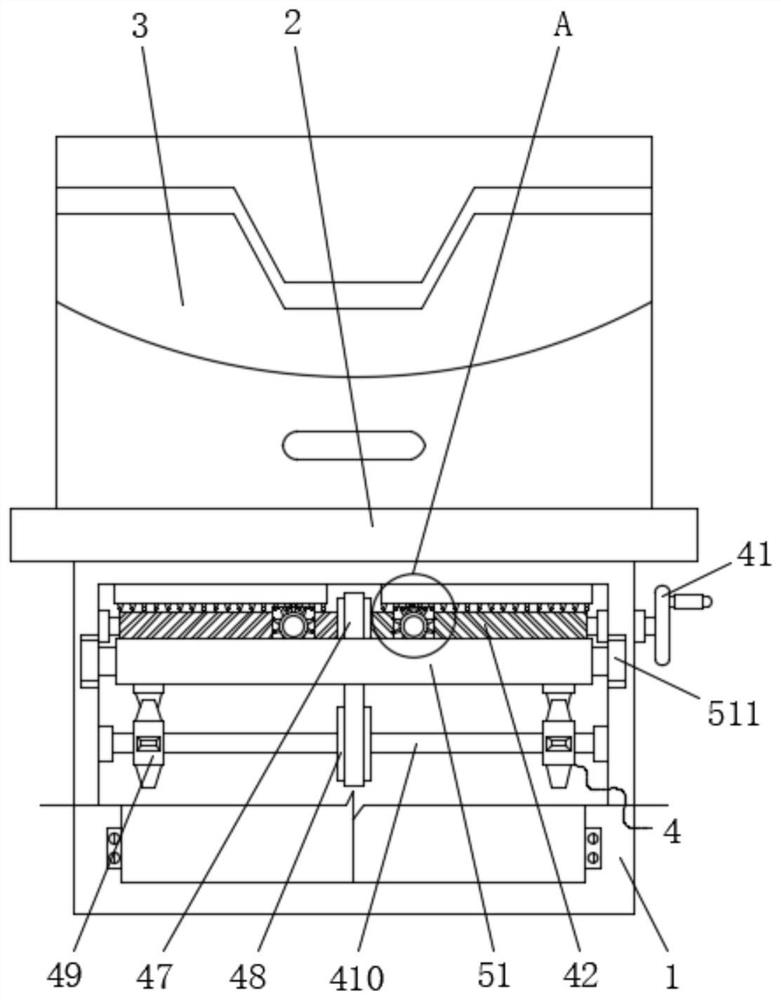
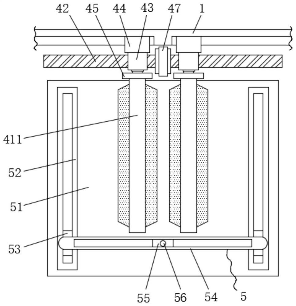
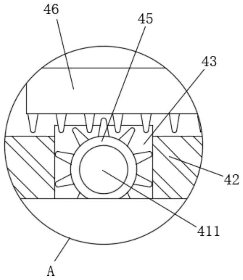
[0041] see Figure 1-6 , the present invention provides a technical solution: a high-speed digital printing machine, comprising a cabinet 1, a platen 2 and a body 3, the upper surface of the cabinet 1 is fixedly connected with a platen 2, and the upper surface of the platen 2 is fixed Connect the organic body 3, the cabinet body 1 is provided with an adjustment mechanism 4, one end of the adjustment mechanism 4 is fixedly connected with one end of the cutting mecha...


PUM


Abstract

The invention discloses a high-speed digital printing machine, and belongs to the technical field of printing machines. The high-speed digital printing machine comprises a cabinet body, a bedplate anda machine body, wherein the upper surface of the cabinet body is fixedly connected with the bedplate, the upper surface of the bedplate is fixedly connected with the machine body, an adjusting mechanism is arranged in the cabinet body, one end of the adjusting mechanism is fixedly connected with one end of a cutting mechanism, the cutting mechanism is located in the cabinet body, an ink supply mechanism is arranged on the back face of the machine body, and a positioning mechanism is arranged in the machine body. By arranging the cutting mechanism, when supporting strips are controlled to moveupwards, connecting rods can be gradually unfolded, meanwhile, T-shaped blocks move to get away from each other and are attracted to two magnet blocks correspondingly, at the moment, the supporting strips can be stably supported, a cutter can be rotated to a proper angle, then the cutter is fixed through bolts, influences on cutting of the printing paper are avoided, the printing paper does not need to be transferred to the cabinet body after being cut on cutting equipment, operation is convenient, and the printing efficiency is greatly improved.

Description

technical field [0001] The invention belongs to the technical field of printing machines, in particular to a high-speed digital printing machine. Background technique [0002] Modern printing machines are generally composed of plate loading, ink application, embossing, paper feeding and other mechanisms. Its principle is to first make the printing plate of the text or image to be printed, install it on the printing machine, and then apply the ink to the place with the text and image on the printing plate manually or by the printing machine, and then transfer it directly or indirectly to the printing plate. In addition, in order to meet people's demand for high-end color printed matter, 8-color group or even 10-color group multi-color double-sided printing, additional in-line post-press processing functions have become various sheet-fed offset printing machines ( Including the development trend of small offset printing machines, DI direct plate-making machines and large offs...

Claims


Application Information

Patent Timeline
IPC IPC(8): B41J2/01B41J2/175B41J11/66B41J29/17
CPCB41J2/01B41J2/17503B41J2/1752B41J11/66B41J29/17
Inventor 谈正晓
Owner 浙江思印科技有限公司
Why Eureka
Try Eureka