
Winding mechanism of full-automatic winding machine

A fully automatic winding machine and winding mechanism technology, which is applied in the direction of conveying filamentous materials, thin material processing, transportation and packaging, etc. Problems such as the working efficiency of the thread machine and the limited use of the winding mechanism, etc., to achieve the effect of high overall convenience and practicability, high overall convenience and efficiency, high efficiency and practicability

Pending Publication Date: 2021-03-12
昆荣机械(昆山)有限公司
View PDF0 Cites 1 Cited by
  • Summary
  • Abstract
  • Description
  • Claims
  • Application Information

AI Technical Summary

Problems solved by technology

[0003] With the general improvement of existing living conditions, the application of automatic winding machines in daily life is more common. Among them, the winding mechanism in the automatic winding machine can help the automatic winding machine to perform fast winding operations. In the existing In daily life, the design structure of the winding mechanism of the fully automatic winding machine is too simple, and the winding efficiency is generally not high. At the same time, it is easy to cause knotting during the winding process. The working efficiency of the automatic winding machine is reduced. At the same time, the use of the existing winding mechanism is relatively large, and different rollers cannot be used to operate according to the needs of the use. The overall convenience, efficiency and practicability are generally not high. Therefore, for The improvement of the winding mechanism of the existing fully automatic winding machine, the design of a new type of winding mechanism of the fully automatic winding machine to change the above-mentioned technical defects, and improve the practicability of the winding mechanism of the overall fully automatic winding machine is particularly important. important

Method used

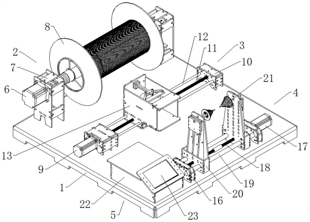
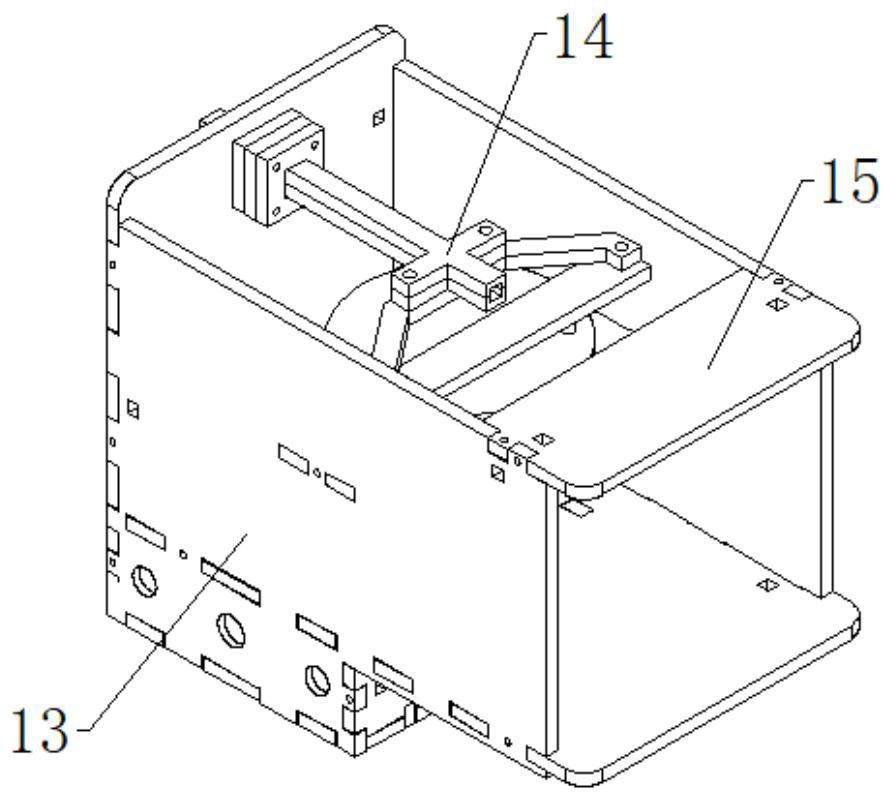
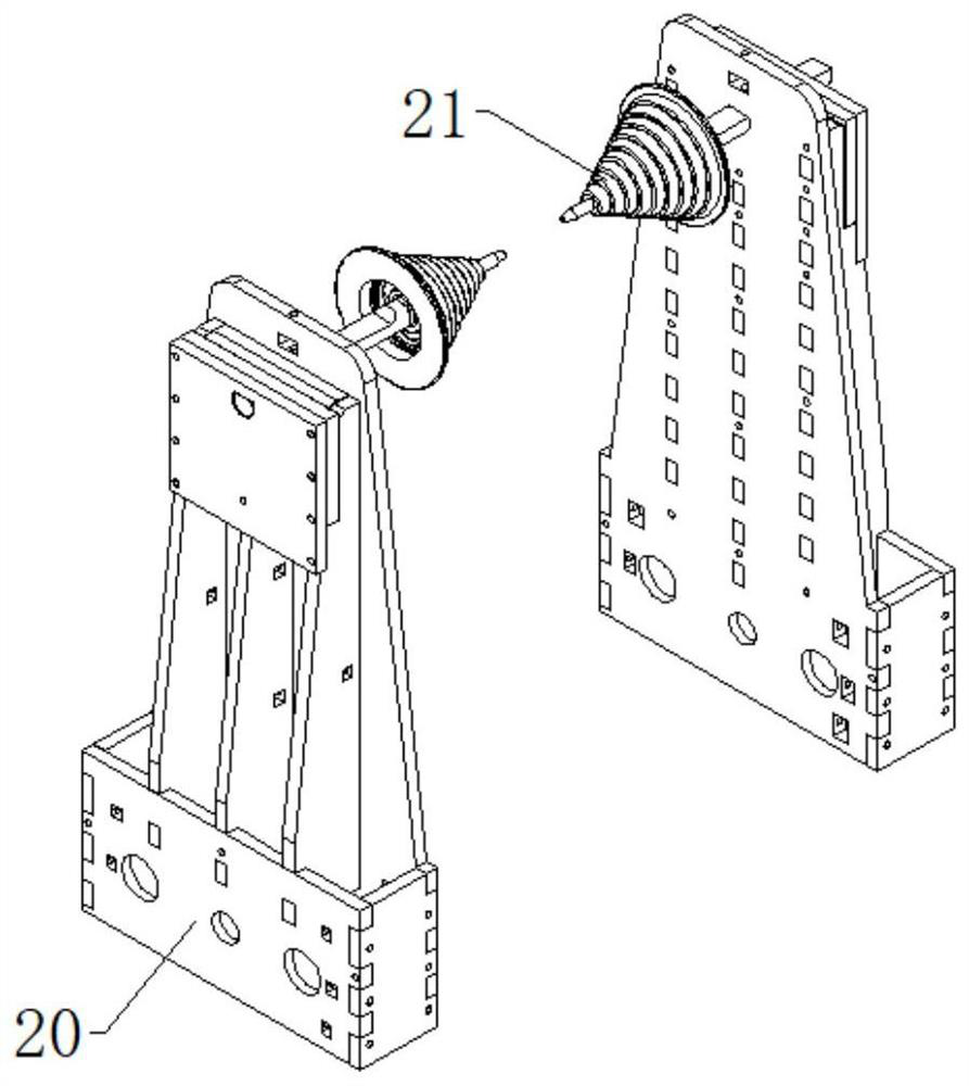

Image

  • Winding mechanism of full-automatic winding machine
  • Winding mechanism of full-automatic winding machine
  • Winding mechanism of full-automatic winding machine

Examples


Embodiment

[0025] Examples, see Figure 1-3 , the present invention provides a technical solution: a winding mechanism of a fully automatic winding machine, including a winding platform 1, and the upper surface of the winding platform 1 is correspondingly provided with a winding mechanism 2, a traction mechanism 3, and a fixing mechanism 4 With the control mechanism 5, the winding mechanism 2 includes a first driving motor 6, a mounting frame 7 and a winding roller 8, and the left side of the mounting frame 7 is correspondingly provided with a first driving motor 6, and the driving end of the first driving motor 6 runs through The left side of mounting frame 7 and extending to the inner side of mounting frame 7 are correspondingly provided with winding roller 8, and traction mechanism 3 comprises second driving motor 9, bearing seat 10, adjusting screw mandrel 11, first sliding rod 12, traction box 13. The traction sleeve 14 and the limit plate 15. The left side of the bearing seat 10 is...


PUM


Abstract

The invention relates to the technical field of full-automatic winding machines, in particular to a winding mechanism of a full-automatic winding machine. The winding mechanism comprises a winding platform, wherein the upper surface of the winding platform is correspondingly provided with a winding mechanism body, a traction mechanism, a fixing mechanism and a control mechanism. The winding mechanism body comprises a first driving motor, a mounting frame and a winding roller. The first driving motor is correspondingly arranged on the left side of the mounting frame, the driving end of the first driving motor penetrates through the left side of the mounting frame and extends to the inner side of the mounting frame to be correspondingly provided with a winding roller. The traction mechanismcomprises a second driving motor, a bearing pedestal, an adjusting lead screw, first sliding rods, a traction box, a traction sleeve and a limiting plate, wherein the second driving motor is correspondingly arranged on the left side of the bearing pedestal. Compared with an existing winding mechanism of the full-automatic winding machine, the winding mechanism of the full-automatic winding machinehas the advantage that the overall convenience, efficiency and practicability of the winding mechanism of the full-automatic winding machine can be improved through the design.

Description

technical field [0001] The invention relates to the technical field of a fully automatic winding machine, in particular to a winding mechanism of a fully automatic winding machine. Background technique [0002] A fully automatic winding machine is a machine that winds a wire-like object onto a specific workpiece. The fully automatic winding machine is a newly developed model. In order to meet the requirements of high efficiency and high output, the fully automatic machine generally adopts multi-head linkage design. Most of the manufacturers refer to the models in Taiwan, China and other places. Design, using programmable controller as the control core of the equipment, cooperate with manipulator, pneumatic control components and executive accessories to complete functions such as automatic wire arrangement, automatic foot binding, automatic thread trimming, automatic loading and unloading of skeletons, etc. The production efficiency of this model is extremely high High, whi...

Claims


Application Information

Patent Timeline
IPC IPC(8): B65H54/44B65H54/30B65H57/12B65H49/30
CPCB65H49/305B65H54/30B65H54/44B65H57/12
Inventor 张昆强
Owner 昆荣机械(昆山)有限公司
Learn More