
Brick paving device for sidewalk pavement construction

A technology for laying bricks and sidewalks, applied in roads, roads, road repair and other directions, can solve the problems of affecting work efficiency, low work efficiency, high labor intensity, etc., to improve accuracy and efficiency, reduce labor, and improve safety. Effect

Inactive Publication Date: 2021-03-12
谢艺云
View PDF0 Cites 3 Cited by
  • Summary
  • Abstract
  • Description
  • Claims
  • Application Information

AI Technical Summary

Problems solved by technology

[0003] At present, most paving bricks on sidewalks are done manually. This method of manual brick laying is labor-intensive and low-efficiency, and the bricks after laying are easy to loosen, causing the bricks to shift and fall, affecting The passage of pedestrians, and due to the manual laying method, the spacing angle of brick laying needs to be measured at all times, which is very inconvenient and affects work efficiency

Method used


Image

  • Brick paving device for sidewalk pavement construction
  • Brick paving device for sidewalk pavement construction
  • Brick paving device for sidewalk pavement construction

Examples


Embodiment 1

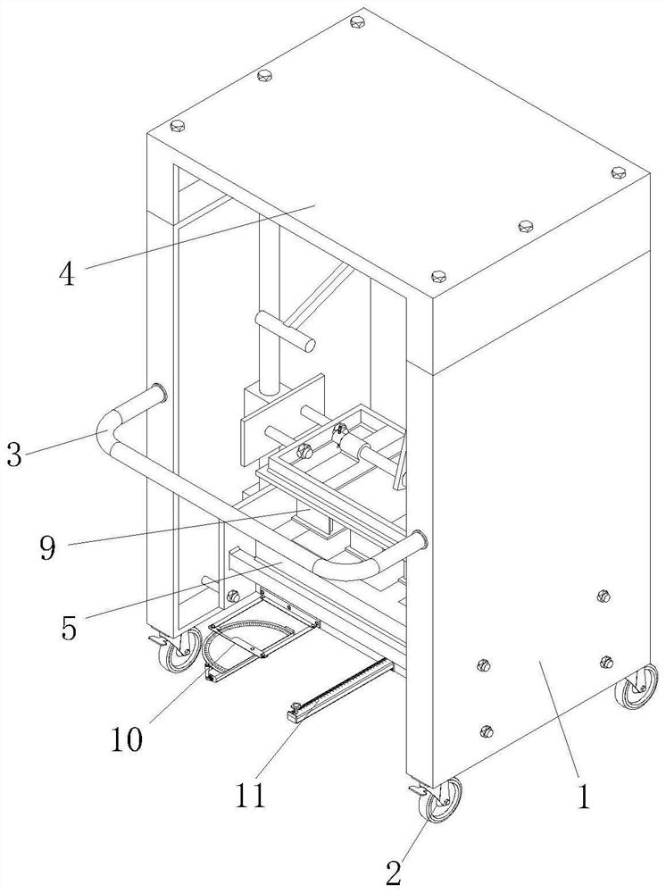
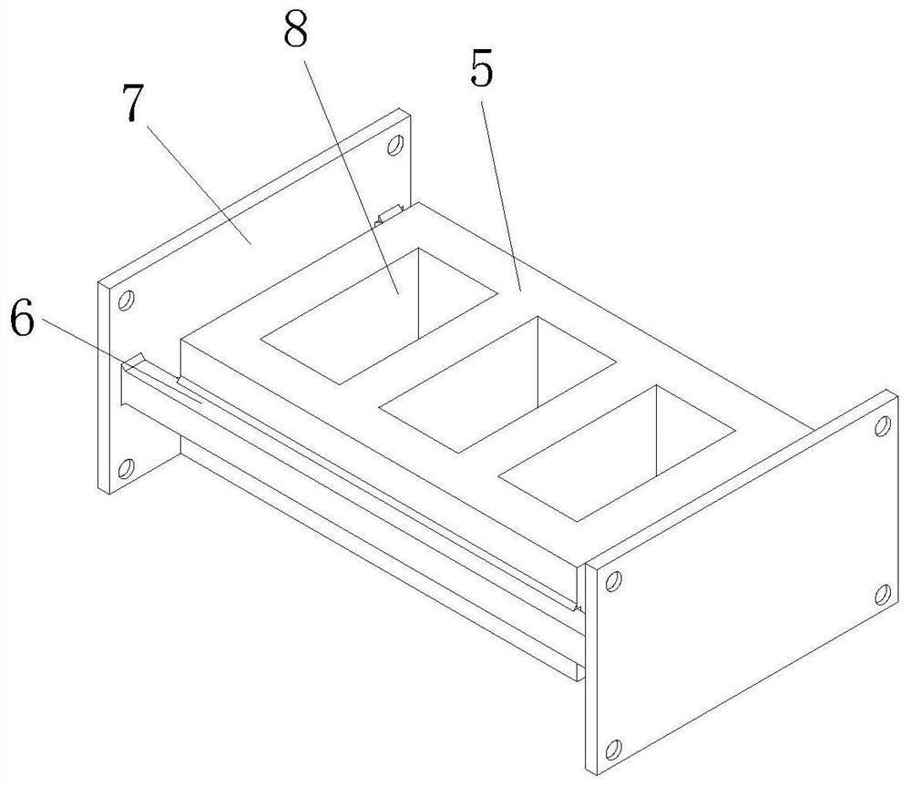
[0032] see Figure 1-2 As shown, the present invention provides a paving device for sidewalk surface construction through improvement, including a body 1, a walking wheel 2, a push rod 3, a top cover 4, a brick laying frame 5, a support horizontal frame 6, and a side fixing plate 7. Brick falling trough 8, manual compaction device 9, angle measuring device 10 and distance measuring device 11, the bottom of the body 1 is provided with a walking wheel 2 for moving, and the middle part of the front end of the body 1 is equipped with a push rod 3, which can be manually Apply force to push, the top cover 4 is installed on the top of the body 1, and the inner bottom of the body 1 is provided with a brick laying frame 5 for laying bricks. The brick laying frame 5, the two ends of the supporting horizontal frame 6 are welded with side fixing plates 7, the two sides of the supporting horizontal frame 6 are fixedly installed with the body 1 through the side fixing plates 7, and the side...

Embodiment 2

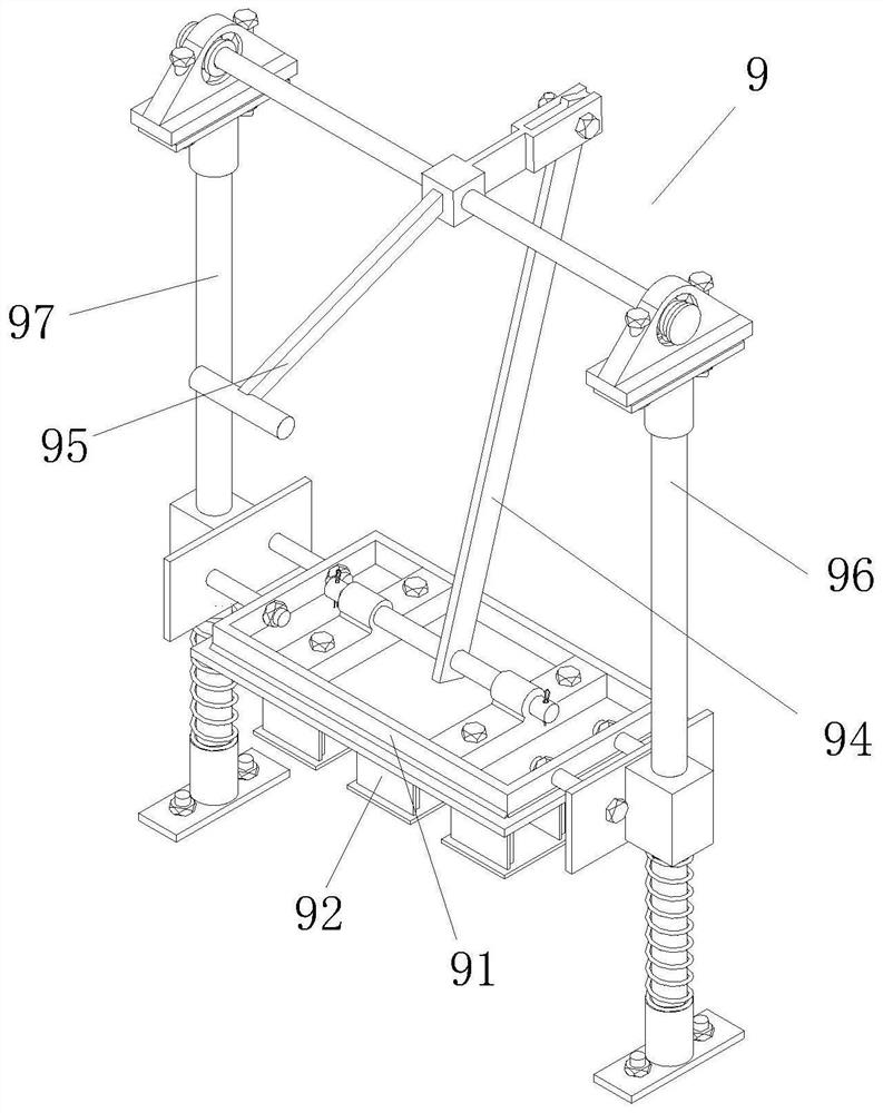
[0039] The present invention provides a brick laying device for sidewalk surface construction through improvement. Three groups of pressing plates 93 are respectively arranged at the bottom of the pressing seat plate 91, and the three groups of pressing plates 93 correspond to three brick falling grooves 8 respectively, and each group of vertical plates 92 and The pressure seat plates 91 are connected by three vertical plates 92 to increase the stability when pressing down and ensure the stable compaction of the bricks. The first rotating shaft 941 runs through the front sides of the movable frame 944 in a transverse direction and is fixed with it, so that the movable The rotation of frame 944 can drive the first rotating shaft 941 to rotate, and the two sides of connecting rod 945 bottom are transversely penetrated with second rotating shaft 946 and fixed therewith, so that connecting rod 945 can drive the second rotating shaft 946 at the bottom to rotate, the first positioning...


PUM


Abstract

The invention discloses a brick paving device for sidewalk pavement construction. The brick paving device comprises a machine body, walking wheels, a pushing rod, a top cover, a brick paving frame, asupporting transverse frame, a side fixing plate, a brick falling groove, a manual compaction device, an angle measuring device and a distance measuring device. The manual compaction device is arranged, when a push handle is pushed, a pressing seat plate can be driven by a pressing mechanism to press downwards, bricks laid on the bottom face are rapidly compacted through a pressing plate, the laidbricks are prevented from loosening, the compaction efficiency is high, compaction work is manually conducted, the hand can be prevented from being pressed when the bricks are placed, and the safetyis greatly improved; and the angle measuring device is arranged, when a brick paving frame deviates, the angle measuring device can be driven to synchronously deviate, after an adjusting frame is manually adjusted, the angle of a measuring swing frame on the angle scale is changed, and therefore the deviation angle can be rapidly known, a brick paving frame can be adjusted to be in the forward direction, and the paving precision is improved.

Description

technical field [0001] The invention relates to the related field of brick-laying tools, in particular to a brick-laying device for pavement construction. Background technique [0002] A sidewalk is a section of a road dedicated to pedestrians that is separated by curbs or guardrails and other similar facilities. Sidewalks are very common in cities, and there are usually sidewalks next to the streets. There are grass or trees between the sidewalk and the motorway in some places, and bricks are usually laid on the sidewalk to facilitate the passage of pedestrians. [0003] At present, most paving bricks on sidewalks are done manually. This method of manual brick laying is labor-intensive and low-efficiency, and the bricks after laying are easy to loosen, causing the bricks to shift and fall, affecting Pedestrians pass, and at the same time, due to the manual laying method, the spacing angle of brick laying needs to be measured at all times, which is very inconvenient and af...

Claims


Application Information

Patent Timeline
Patent Type & Authority Applications(China)
IPC IPC(8): E01C19/52E01C23/01
CPCE01C19/52E01C23/01
Inventor 谢艺云
Owner 谢艺云
Learn More