Steel box girder overhaul hole structure convenient for overhauling

It is a technology that facilitates maintenance and steel box girder. It is applied to bridges, bridge parts, and bridge construction. It can solve problems such as difficulty in entering bridges for maintenance personnel or equipment, hidden dangers in operation and maintenance, and occupation of lanes under bridges, so as to ensure structural operation. Safety, simplify maintenance difficulty, reduce the effect of opening and closing difficulty

Pending Publication Date: 2021-03-12
BEIJING GENERAL MUNICIPAL ENG DESIGN & RES INST
View PDF0 Cites 1 Cited by
  • Summary
  • Abstract
  • Description
  • Claims
  • Application Information

AI Technical Summary

Problems solved by technology

For steel girder bridges with complex space under the bridge or high bridge height, the inspection holes are set at the bottom and side of the girder, which is not convenient for maintenance, which will cause the following inconveniences: 1. Temporary measures such as erecting brackets or using elevators for internal maintenance of steel girders Only personnel can enter; 2. Set up supports or use elevators to occupy the driveway under the bridge, which will affect the traffic under the bridge; 3. It is difficult for maintenance personnel or equipment to enter the interior of the bridge, and there are potential safety hazards in the operation and maintenance under the bridge
The above difficulties can be solved by using the bridge deck space (isolation belt or sidewalk) to set up inspection holes, but the current technical measures cannot fundamentally solve the problems of watertightness of the bridge deck inspection holes and the aesthetics of the bridge deck

Method used


Image

  • Steel box girder overhaul hole structure convenient for overhauling
  • Steel box girder overhaul hole structure convenient for overhauling
  • Steel box girder overhaul hole structure convenient for overhauling

Examples


Embodiment Construction

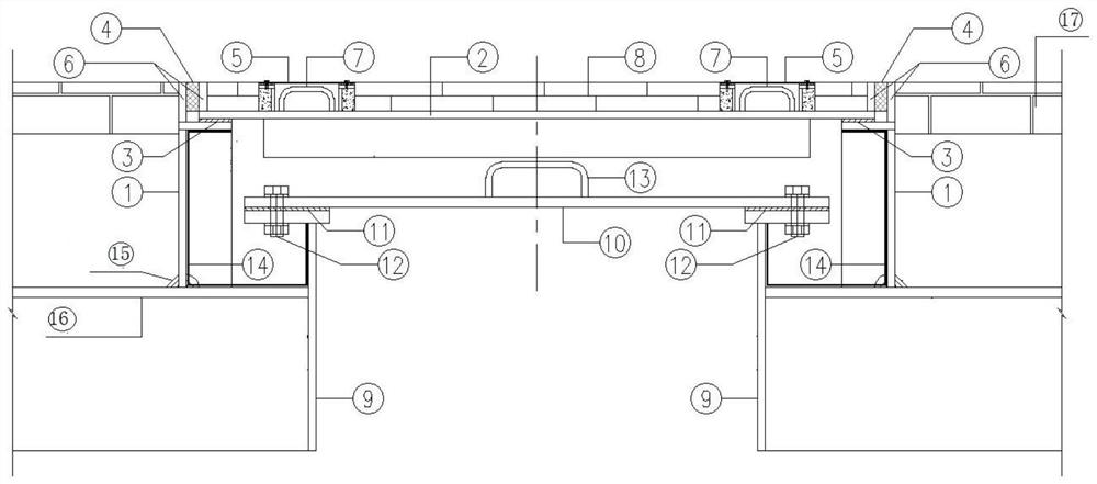
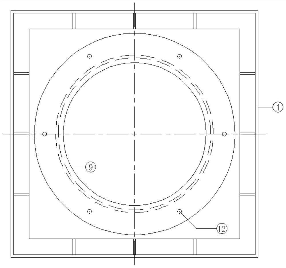
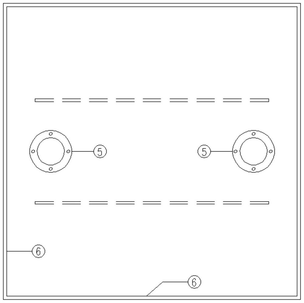
[0019] Concrete structure of the present invention sees figure 1 , figure 2 , image 3 shown. The double-layer maintenance wellhead design includes an outer rectangular wellhead device and an inner circular wellhead device. The double-layer wellheads are equipped with replaceable water-tight sealing devices to prevent the intrusion of dust and liquid, and greatly improve the guarantee rate of watertightness of the maintenance hole.

[0020] The outer wellhead device includes an outer rectangular wellhead (1), an outer rectangular maintenance manhole cover (2), a first waterproof rubber pad (3) is provided between the wellhead and the well cover, and a replaceable type waterstop kit(4). Among them, the water-stop kit is composed of extruded rubber belt and fillable and replaceable caulking water-stop liquid rubber base material, which can maintain good airtightness and waterproofness of the inspection hole under expansion, vibration and temperature changes.

[0021] The in...


PUM


Abstract

The invention discloses a steel box girder overhaul hole structure convenient for overhauling. The steel box girder overhaul hole structure comprises an outer-layer rectangular wellhead device and aninner-layer circular wellhead device, wherein double layers of wellhead are provided with replaceable water stop sealing devices; the outer side wellhead device comprises an outer side rectangular wellhead and an outer side rectangular overhaul well lid, a first waterproof rubber pad is arranged between the wellhead and the well lid, and a replaceable water stop kit is arranged between the wellhead and a groove in the end part of the well lid; and the inner side wellhead device comprises an inner side circular wellhead and an inner side circular overhaul well lid, a second waterproof rubber pad is arranged between the wellhead and the well lid, the inner side wellhead protrudes out of a steel box girder, and the space between the inner side wellhead and the outer side wellhead is coated with a waterproof layer. According to the steel box girder overhaul hole structure convenient for overhauling, the overhaul hole structure is arranged in a bridge floor overhaul space (such as an isolation belt or a pedestrian way), so that the technical problem of urban steel girder overhaul is effectively solved, and the technical problems of water tightness, bridge floor attractiveness and the like of the overhaul hole structure can be solved.

Description

technical field [0001] The invention belongs to the improvement technology of bridge structure. Background technique [0002] At present, steel box girder inspection holes are usually set at the bottom and sides of steel box girder girders, which are more suitable for steel girder bridges with no inspection space on the bridge deck. For steel girder bridges with complex space under the bridge or high bridge height, the inspection holes are set on the bottom and side of the girder, which is not convenient for maintenance, which will cause the following inconveniences: 1. Temporary measures such as erecting supports or using elevators for internal maintenance of steel girders Only personnel can enter; 2. Set up supports or use elevators to occupy the lanes under the bridge, affecting the traffic under the bridge; 3. It is difficult for maintenance personnel or machinery and equipment to enter the interior of the bridge, and there are potential safety hazards for under-bridge o...

Claims


Application Information

Patent Timeline
Patent Type & Authority Applications(China)
IPC IPC(8): E02D29/12E02D29/14E01D19/08
CPCE01D19/083E02D29/12E02D29/121E02D29/14E02D29/1418E02D29/1427E02D29/1481E02D29/149
Inventor 李东李盼到安邦程京伟汪岩王美王犇王紫玉温磊庞兴张喆陈峥嵘
Owner BEIJING GENERAL MUNICIPAL ENG DESIGN & RES INST
Why Eureka
Try Eureka