Integrated main speed reducer

A main reducer, integrated technology, applied in the field of auto parts, can solve the problems of large axial space and heavy weight, and achieve the effects of reducing the number of parts, improving life, and short axial distance

Pending Publication Date: 2021-03-12
SHAANXI HANDE AXLE CO LTD
View PDF0 Cites 0 Cited by
  • Summary
  • Abstract
  • Description
  • Claims
  • Application Information

AI Technical Summary

Problems solved by technology

[0003] At present, the main reducer assembly and the transfer case assembly are mostly two independent assemblies, with large axial space and heavy weight

Method used


Image

  • Integrated main speed reducer
  • Integrated main speed reducer
  • Integrated main speed reducer

Examples


Embodiment 1

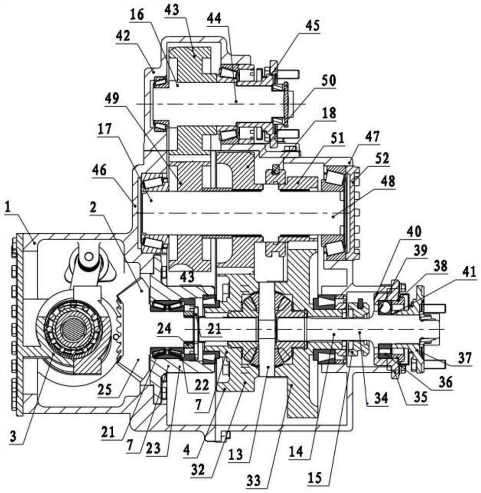
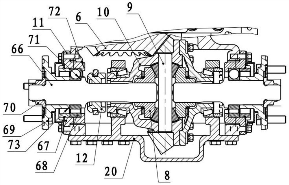
[0032] Embodiment 1: The structure of the main reducer according to the present invention, including the housing assembly 1, the main reducer assembly 2, the inter-wheel differential assembly 3, the inter-axle differential assembly 4, the transfer case assembly into; the final drive assembly 2, the inter-wheel differential assembly 3, the inter-axle differential assembly 4, and the transfer case assembly are all installed inside the shell assembly 1.

[0033] The housing assembly 1 is a structure in which the back cover and tile cover are designed as one, forming the back cover 20, which is beneficial to shorten the axial distance and reduce the space requirement.

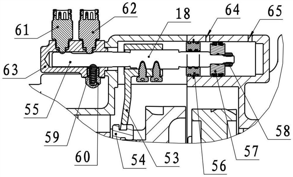
[0034] The main reducer assembly 2 includes a bevel gear pair 6, a main cone bearing assembly 7, the main cone bearing assembly 7 is assembled in the inner cavity of the housing assembly 1, and the main cone bearing assembly 7 is connected with the housing Adjusting washers are used between the assembly surfaces of...


PUM


Abstract

The invention relates to an integrated main speed reducer which comprises a shell assembly. The shell assembly comprises a speed reducer shell and a gap bridge box. A main speed reducer assembly, an inter-wheel differential mechanism assembly, an inter-axle differential mechanism assembly and a transfer case assembly are installed in an inner cavity of the shell assembly, and the transfer case assembly comprises a second axle system assembly. The second axle system assembly is mounted above the inter-axle differential mechanism assembly and engaged with the inter-axle differential mechanism assembly through a second-stage low-gear driving cylindrical gear, and the main speed reducer assembly is mounted at the front end of the inter-axle differential mechanism assembly. An inter-wheel differential mechanism is mounted in the main speed reducer assembly. According to the integrated main speed reducer, the problems that in the prior art, most of a main speed reducer assembly and a transfer case assembly are two independent assemblies, the axial space is large, and the weight is large are solved.

Description

technical field [0001] The invention belongs to the field of auto parts, in particular to an integrated final reducer. Background technique [0002] The final drive is a mechanism that can change the torque and speed in the drive axle. Increase the torque from the transmission or universal joint transmission, while reducing the speed and changing the direction of torque transmission. The transfer case is a device that distributes the power of the engine, and can output power to the rear axle, or to the front / rear axle at the same time. [0003] At present, the main reducer assembly and the transfer case assembly are mostly two independent assemblies with large axial space and heavy weight. Contents of the invention [0004] The technical problem solved by the invention lies in the problem that the final reducer assembly and the transfer case assembly are mostly two mutually independent assemblies. [0005] The present invention is achieved through the following technica...

Claims


Application Information

Patent Timeline
Patent Type & Authority Applications(China)
IPC IPC(8): F16H57/021F16H57/023F16H57/037
CPCF16H57/021F16H57/023F16H57/037F16H2057/02052F16H2057/02086F16H2057/02091F16H2057/02095
Inventor 赵冰
Owner SHAANXI HANDE AXLE CO LTD
Why Eureka
Try Eureka