Probe sealing structure for high-pressure fluid pipeline

A high-pressure fluid and sealing structure technology, which is applied in engine sealing, piping system, gas/liquid distribution and storage, etc., can solve problems such as no sealing structure, easy leakage, poor safety performance, etc., to improve safety and meet Sealing requirements, the effect of increasing the pressing force

Active Publication Date: 2021-03-12
INST OF ENGINEERING THERMOPHYSICS - CHINESE ACAD OF SCI
View PDF6 Cites 0 Cited by
  • Summary
  • Abstract
  • Description
  • Claims
  • Application Information

AI Technical Summary

Problems solved by technology

This technology requires operations such as drilling and welding on the outer wall of the pipeline, which adversely affects the local pressure bearing capacity of the pipeline; in addition, the sealing of this technology is only completed by the gland pressing the sealing packing, and there is no special sealing structure designed. The pressure is limited, it is easy to leak, and the safety performance is poor, so it cannot meet the probe measurement requirements in high-pressure environments

Method used


Image

  • Probe sealing structure for high-pressure fluid pipeline
  • Probe sealing structure for high-pressure fluid pipeline
  • Probe sealing structure for high-pressure fluid pipeline

Examples


Embodiment Construction

[0028] In order to make the objectives, technical solutions and advantages of the present invention clearer, the technical solutions in the embodiments of the present invention will be described in more detail below in conjunction with the drawings in the embodiments of the present invention. In the drawings, the same or similar reference numerals denote the same or similar elements or elements having the same or similar functions throughout. The described embodiments are some, but not all, embodiments of the invention. The embodiments described below by referring to the figures are exemplary and are intended to explain the present invention and should not be construed as limiting the present invention. Based on the embodiments of the present invention, all other embodiments obtained by persons of ordinary skill in the art without creative efforts fall within the protection scope of the present invention. The structure and technical solutions of the present invention will be ...


PUM


Abstract

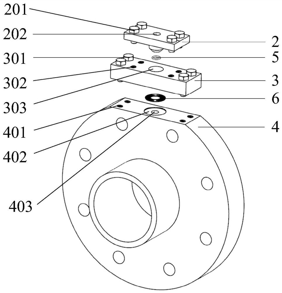
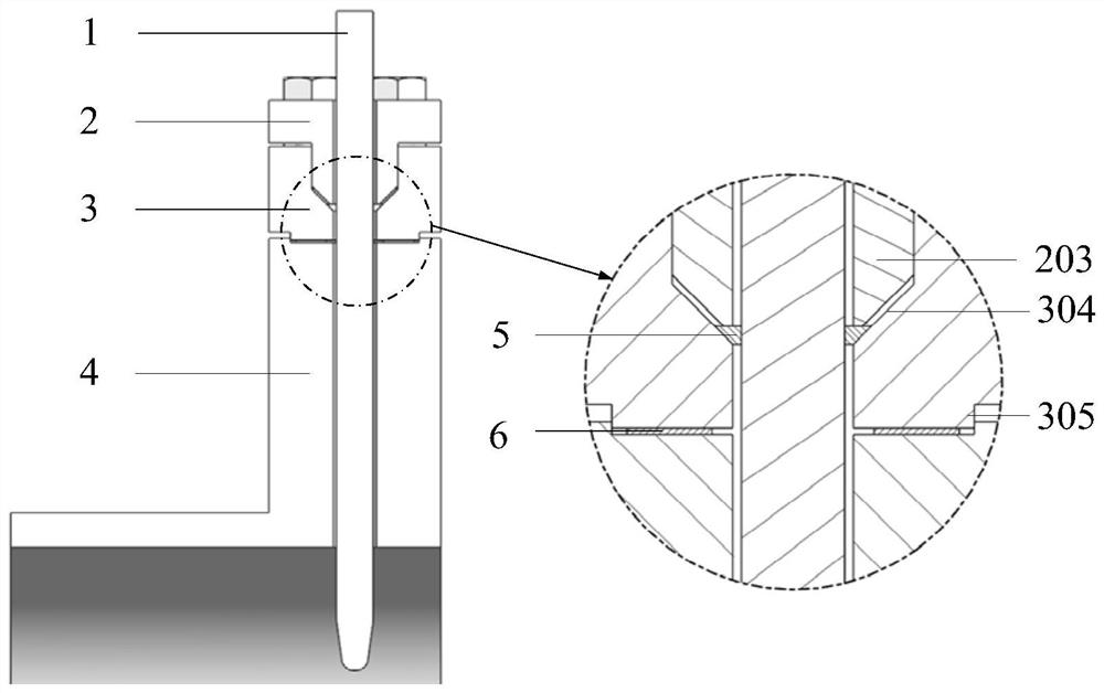
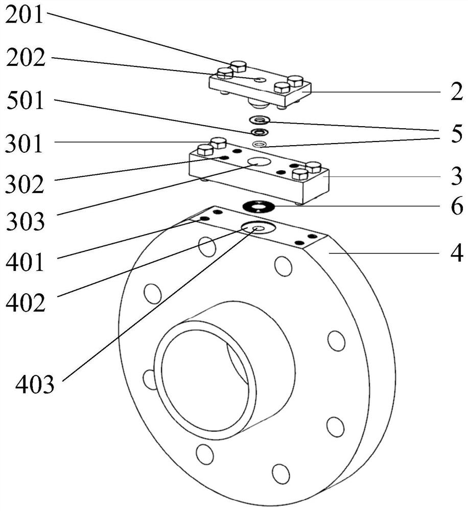
The invention relates to a probe sealing structure for a high-pressure fluid pipeline. The probe sealing structure comprises a probe hole, a sealing cover plate, a fastening cover plate and other sealing parts positioned on a flange plate, and a sealing gasket, an elastic sealing ring and other sealing media for sealing high-pressure fluid leaked from the probe hole. The probe hole is formed in the outer end face of the flange in the radial direction, so that a probe sleeve located on the outer wall of a pipeline in the prior art is omitted, and damage to the high-pressure pipeline due to drilling, welding and the like in the sleeve mounting process is avoided; and meanwhile, the sealing components such as the sealing cover plate and the fastening cover plate are designed for the high-pressure environment in the pipeline, and also the high-pressure fluid leaked from the probe hole is sealed by arranging auxiliary sealing structures matched with a pressing ring, a sealing ring, a sealing groove and the like, so that the sealing effect of a probe in the high-pressure environment is enhanced, and the stability and reliability of the structure are improved.

Description

technical field [0001] The invention relates to the fields of chemical industry and aviation, in particular to a probe sealing structure in a high-pressure environment, which is used for flow field tests in pipelines. Background technique [0002] Compressors, expanders, etc. are energy and power equipment commonly used in the chemical industry (such as compressed air energy storage systems) or aviation (such as aero-engines). The temperature and pressure of the working fluid are measured in real time. [0003] In the prior art, the measuring hole of the probe is arranged on the pipe wall, the probe fixing sleeve is connected to the outer wall of the pipe by welding, and the seal of the probe is completed by pressing the sealing packing with the gland. This technology requires operations such as drilling and welding on the outer wall of the pipeline, which adversely affects the local pressure bearing capacity of the pipeline; in addition, the sealing of this technology is o...

Claims


Application Information

Patent Timeline
Patent Type & Authority Applications(China)
IPC IPC(8): F16J15/06F16J15/10F17D5/00
CPCF16J15/061F16J15/062F16J15/10F17D5/00F17D5/005
Inventor 邵梓一李文张雪辉陈海生
Owner INST OF ENGINEERING THERMOPHYSICS - CHINESE ACAD OF SCI
Why Eureka
Try Eureka