
Dryer with fluff removing function for cotton and wool cloth

A technology for dryers and wool cloth, applied in the field of textile production, can solve the problems of poor quality cotton wool, low efficiency, and affecting cotton cloth processing, and achieve the effect of avoiding fluff flying and improving drying efficiency

Inactive Publication Date: 2021-03-12
郑州市林慕商贸有限公司
View PDF8 Cites 2 Cited by
  • Summary
  • Abstract
  • Description
  • Claims
  • Application Information

AI Technical Summary

Problems solved by technology

[0003] In the drying process of cotton cloth, the existing drying device usually adopts one-sided drying, which makes the two sides of the cotton cloth dry unevenly, and usually needs to be dried twice, which makes the drying efficiency relatively high. At the same time, there will be a certain amount of fluff on the surface of the cotton cloth after drying. These fluffs will affect the subsequent processing of the cotton cloth when they are attached to the cotton cloth, so that the quality of the cotton wool after processing is poor.

Method used


Image

  • Dryer with fluff removing function for cotton and wool cloth
  • Dryer with fluff removing function for cotton and wool cloth
  • Dryer with fluff removing function for cotton and wool cloth

Examples


Embodiment 1

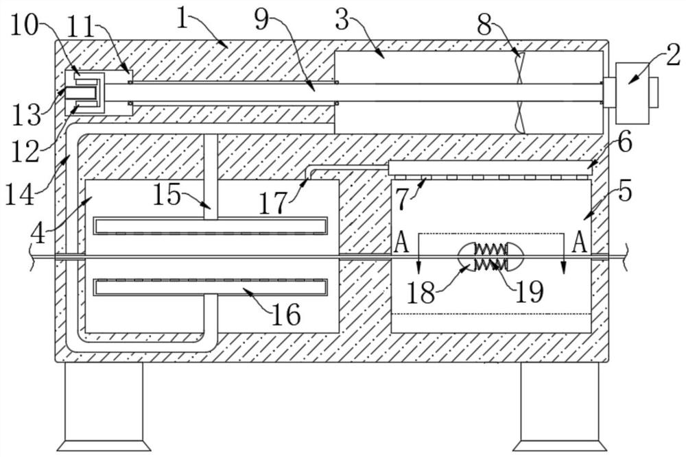
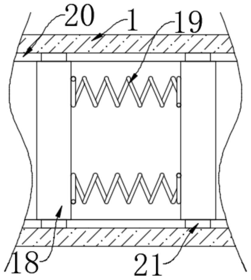
[0022] refer to Figure 1-2 , a dryer for cotton and wool fabrics with the function of delinting, comprising a housing 1, in which a drying chamber 4 and a delinting chamber 5 are sequentially arranged from left to right, and a suction chamber is arranged in the housing 1 3. The suction chamber 3 is located above the delint chamber 5, and the housing 1 is provided with a power generation chamber 11, which is located on the left side of the suction chamber 3;

[0023] Drying mechanism, the drying mechanism includes a hot air blower 2 arranged at the right end of the housing 1, the air outlet of the hot air blower 2 is connected to the air suction cavity 3, and two hollow plates 16 are symmetrically arranged in the drying chamber 4, and two hollow plates 16 are arranged symmetrically. The opposite sides of the plates 16 are provided with a plurality of air holes, and the air holes on the two hollow plates 16 are relatively arranged to facilitate the drying of both sides of the c...

Embodiment 2

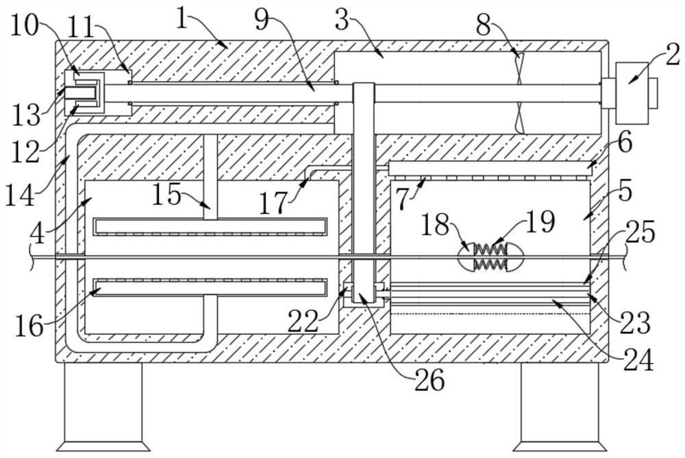
[0030] refer to image 3The difference between this embodiment and Embodiment 1 is that a transmission chamber 22 is provided in the housing 1, and a second rotating rod 23 is horizontally provided in the transmission chamber 22, and the two ends of the second rotating rod 23 are connected to The inner walls on both sides are rotationally connected, and the transmission structure 26 is connected between the first rotating rod 9 and the second rotating rod 23. The transmission structure 26 includes two transmission wheels installed on the first rotating rod 9 and the second rotating rod 23 respectively. The two transmission wheels are connected by a transmission belt, and the right end of the second rotating rod 23 extends into the fleece removal chamber 5 and is rotationally connected with the right inner wall of the fleece removal chamber 5, and the second rotation rod 23 is located in the fleece removal chamber 5 Part of the outer wall is fixedly connected with a silk layer ...


PUM


Abstract

The invention discloses a dryer with a fluff removing function for cotton and wool cloth. The dryer comprises a shell, a drying chamber and a fluff removing chamber are sequentially arranged in the shell from left to right, an air suction cavity is formed in the shell and located above the fluff removing chamber, and a power generation cavity is formed in the shell and located at the left side ofthe air suction cavity; a drying mechanism is further arranged, the drying mechanism comprises an air heater arranged at the right end of the shell, an air outlet of the air heater is communicated with the air suction cavity, two hollow plates are symmetrically arranged in the drying chamber, and the air suction cavity is communicated with the hollow plate located at the lower portion through an air outlet pipe; and the upper end of the hollow plate located at the upper portion is communicated with the air outlet pipe through a vertical pipe. According to the dryer, double-sided drying can beconducted on the cotton cloth in the drying process, the cotton cloth drying efficiency is improved, meanwhile, fluff on the dried cotton cloth is scraped off to be collected, and therefore subsequentprocessing of the cotton cloth is facilitated.

Description

technical field [0001] The invention relates to the field of textile production, in particular to a dryer for cotton and wool fabrics with the function of removing velvet. Background technique [0002] Cotton cloth is a cloth made of cotton yarn, which is the general term for all kinds of cotton textiles. Cotton cloth is a necessity in people's daily life. During the processing of cotton cloth, it is necessary to dry the printed and dyed cotton cloth, so that the cotton cloth is The moisture on the surface evaporates, which is convenient for the preservation of cotton cloth, but the existing cotton cloth drying device still has the following problems: [0003] In the drying process of cotton cloth, the existing drying device usually adopts one-sided drying, which makes the two sides of the cotton cloth dry unevenly, and usually needs to be dried twice, which makes the drying efficiency relatively high. At the same time, there will be a certain amount of fluff on the surface...

Claims


Application Information

Patent Timeline
Patent Type & Authority Applications(China)
IPC IPC(8): F26B13/28F26B21/00F26B25/00F26B25/04F26B25/12F26B25/18
CPCF26B13/28F26B21/001F26B25/18F26B25/12F26B25/003F26B25/04
Inventor 陈娅茹曹雪丽许长建
Owner 郑州市林慕商贸有限公司
Learn More