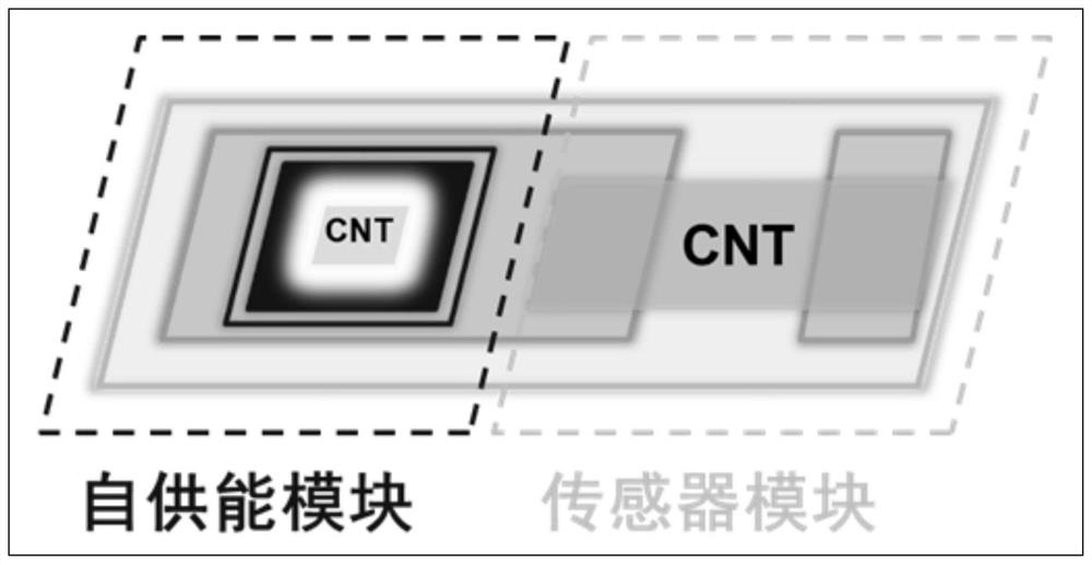
Fabrication method of self-powered gas sensor based on single-walled carbon nanotubes
A technology of single-walled carbon nanotubes and gas sensors, which is applied in semiconductor devices, instruments, scientific instruments, etc., can solve the problems such as the difficulty of battery replacement, and achieve the effects of low cost, improved resolution, and easy mass production
- Summary
- Abstract
- Description
- Claims
- Application Information
AI Technical Summary
Problems solved by technology
Method used
Image

Examples
Embodiment 1
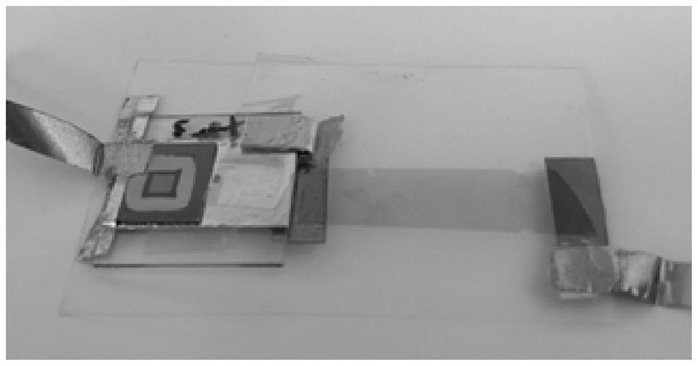
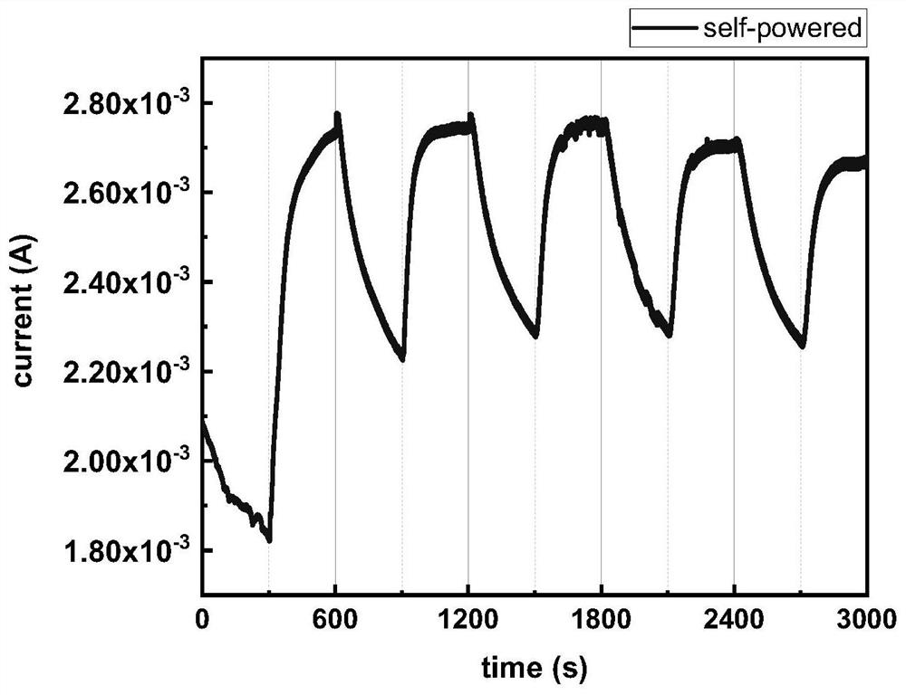
[0036] Embodiment 1: Using a gas sensor testing system, the self-powered gas sensor prepared above was put into a transparent sensor testing system. Under light conditions, no external power supply is applied, and the self-powered gas sensor of the present invention is tested against 100ppm NO 2 response performance.
[0037] Under the condition of light, the self-powered sensor directly converts light energy into electrical energy to drive the sensor components to work, and obtains a response performance curve that is not weaker or even better than the external power supply ( image 3 ), compared with the condition of external power supply, the integrated self-powered gas sensor has a more obvious response amplitude, faster response time and recovery time, and a very weak curve shift, which is closer to the ideal square wave curve.
Embodiment 2
[0038] Embodiment 2: Using the gas sensor testing system, the prepared flexible self-powered sensor is put into a transparent sensor testing system. Under light conditions, no external power supply is applied, and the self-powered gas sensor of the present invention is tested against 100ppmNH 3 response performance.
[0039] The flexible self-powered sensor directly converts light energy into electrical energy under illumination conditions, drives the sensor assembly to work, and obtains a curve similar to that of Example 1, the difference is that Example 1 has a NO of 100ppm 2 Under the atmosphere, the current increases; and in Example 2, when the sensor is exposed to 100ppm of NH 3 Atmosphere, the current decreases.
Embodiment 3
[0040] Embodiment 3: Using a gas sensor testing system, the prepared sensor is put into a transparent cavity of the sensor testing system. Under conditions such as illumination, do not apply external power supply, test self-powered gas sensor of the present invention to 100ppmO 2 response performance.
[0041] Under the condition of light, the flexible self-powered sensor directly converts light energy into electric energy to drive the sensor component to work, and obtains a response curve similar to that of Example 1.
PUM
| Property | Measurement | Unit |
|---|---|---|
| diameter | aaaaa | aaaaa |
| pore size | aaaaa | aaaaa |
| thickness | aaaaa | aaaaa |
Abstract
Description
Claims
Application Information
 - R&D
- Intellectual Property
- Life Sciences
- Materials
- Tech Scout
- Unparalleled Data Quality
- Higher Quality Content
- 60% Fewer Hallucinations
Browse by: Latest US Patents, China's latest patents, Technical Efficacy Thesaurus, Application Domain, Technology Topic, Popular Technical Reports.
© 2025 PatSnap. All rights reserved.Legal|Privacy policy|Modern Slavery Act Transparency Statement|Sitemap|About US| Contact US: help@patsnap.com