
A Fault Identification Method for EMU Traction Motors and Foreign Objects Clamped Between Axles

A traction motor and fault identification technology, applied in the field of image processing, can solve problems such as poor accuracy, and achieve the effects of increasing accuracy, reducing network overfitting, and improving detection efficiency

Active Publication Date: 2021-08-24
HARBIN KEJIA GENERAL MECHANICAL & ELECTRICAL CO LTD
View PDF21 Cites 0 Cited by
  • Summary
  • Abstract
  • Description
  • Claims
  • Application Information

AI Technical Summary

Problems solved by technology

[0004] The purpose of the present invention is to propose a fault identification method for traction motors and foreign objects between axles of EMUs in view of the problem of poor accuracy in the fault detection of foreign objects caught between traction motors and shafts in the prior art

Method used


Image

  • A Fault Identification Method for EMU Traction Motors and Foreign Objects Clamped Between Axles
  • A Fault Identification Method for EMU Traction Motors and Foreign Objects Clamped Between Axles
  • A Fault Identification Method for EMU Traction Motors and Foreign Objects Clamped Between Axles

Examples


specific Embodiment approach 1

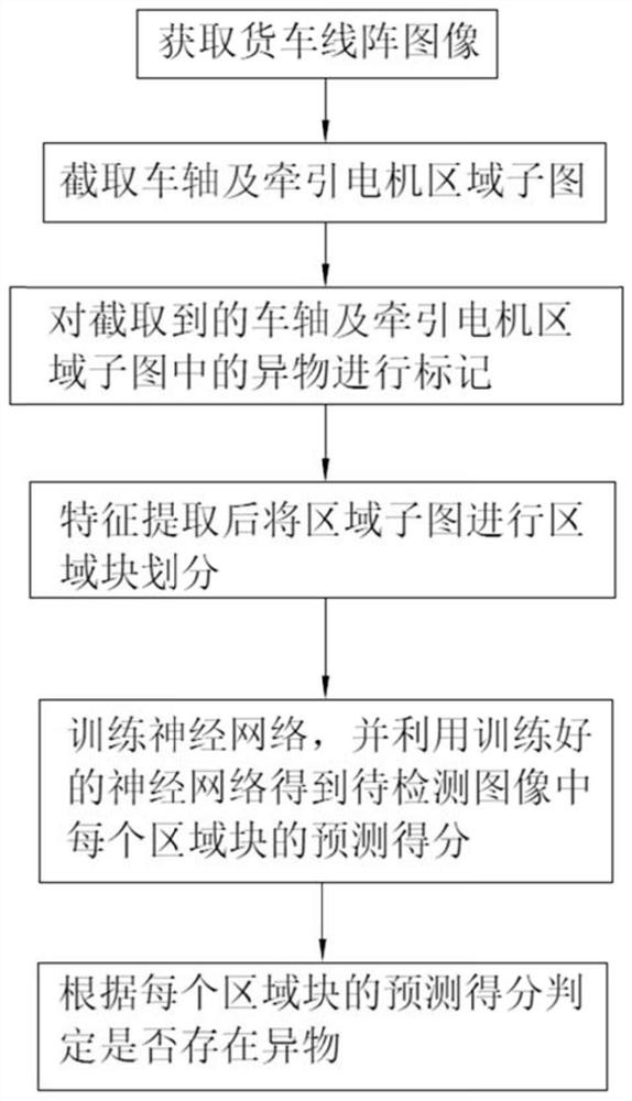
[0037] Specific implementation mode one: refer to image 3 Describe this embodiment in detail, a fault identification method for a traction motor of an EMU and a foreign object caught between shafts in this embodiment, comprising the following steps:

[0038] Step 1: Obtain the 2D linear array grayscale image of the truck;

[0039] Step 2: According to the 2D linear array grayscale image of the truck, the sub-image of the axle and traction motor area is intercepted;

[0040] Step 3: Mark the foreign objects in the intercepted axle and traction motor area sub-images;

[0041] Step 4: Perform feature extraction on the marked axle and traction motor area submaps to obtain feature maps, then divide the feature maps into multiple area blocks, and use the divided feature maps as the training set to train the neural network;

[0042] Step 5: input the image to be detected into the trained neural network, and obtain the prediction score of each block corresponding to the image to be...

specific Embodiment approach 2

[0056] Specific embodiment 2: This embodiment is a further description of specific embodiment 1. The difference between this embodiment and specific embodiment 1 is that in step 2, the axle and traction motor area submaps are intercepted and provided based on prior knowledge, hardware and framework. The wheelbase information is used to intercept the submap of the axle and traction motor area.

specific Embodiment approach 3

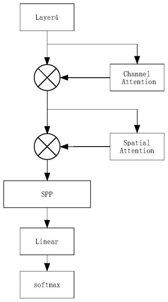
[0057] Embodiment 3: This embodiment is a further description of Embodiment 2. The difference between this embodiment and Embodiment 2 is that the core of the neural network is Resnet50, and layer4 in Resnet50 outputs a feature map.

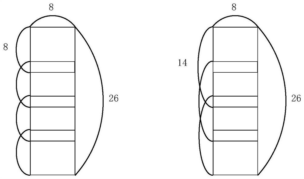
[0058] This algorithm uses Resnet50 as the backbone, and uses the output of layer4 in Resnet50 as the feature map. The feature map is divided into regions to obtain region features.


PUM


Abstract

A fault identification method for a traction motor of an EMU and a foreign object caught between shafts, which relates to the field of image processing technology, and aims at the problem of poor accuracy in the fault detection of the foreign matter caught between the traction motor and the shaft in the prior art, comprising the following steps Step 1: Obtain the 2D linear array grayscale image of the truck; Step 2: Intercept the sub-image of the axle and traction motor area according to the 2D linear array grayscale image of the truck; Step 3: Mark the foreign objects in the sub-image of the axle and traction motor area; Step 4: Divide the marked image into multiple regions, and use the divided images as a training set to train the neural network; Step 5: Input the image to be detected into the trained neural network to obtain the prediction of each region block Score; Step 6: According to the prediction score of each block, determine whether there is any foreign object caught between the traction motor and the shaft of the EMU.

Description

technical field [0001] The invention relates to the technical field of image processing, in particular to a fault identification method for a traction motor of an EMU and a foreign object caught between axles. Background technique [0002] In the direction of railway safety, the traditional method is to find the fault point of the train through manual observation after the detection equipment takes pictures. This approach enables fault detection while the vehicle is moving without stopping. However, manual observation has disadvantages such as fatigue, high intensity, and need for training. At this stage, more and more things can be replaced by machines. Machines have the characteristics of low cost, unified rules, and 24-hour fatigue-free. Therefore, it is feasible to use image recognition technology to replace traditional manual inspection. [0003] There are many kinds of foreign objects caught between traction motors and shafts, and the sizes are different. It is diff...

Claims


Application Information

Patent Timeline
Patent Type & Authority Patents(China)
IPC IPC(8): G06K9/00G06N3/04G06N3/08
CPCG06N3/08G06V20/584G06N3/047G06N3/048G06N3/045
Inventor 汤岩
Owner HARBIN KEJIA GENERAL MECHANICAL & ELECTRICAL CO LTD
Learn More