Multi-connecting rod sliding block mechanism for locking machine

A multi-link, locking machine technology, applied in the direction of connection, feeding device, manufacturing tools, etc., can solve the problems of increased workload of workers, increased labor costs, and easy locking of shrapnel, so as to reduce losses, reduce Labor cost, flexible use of effects

Active Publication Date: 2021-03-12
AMPHENOL (XIAMEN) HIGH SPEED CABLE CO LTD
View PDF2 Cites 0 Cited by
  • Summary
  • Abstract
  • Description
  • Claims
  • Application Information

AI Technical Summary

Problems solved by technology

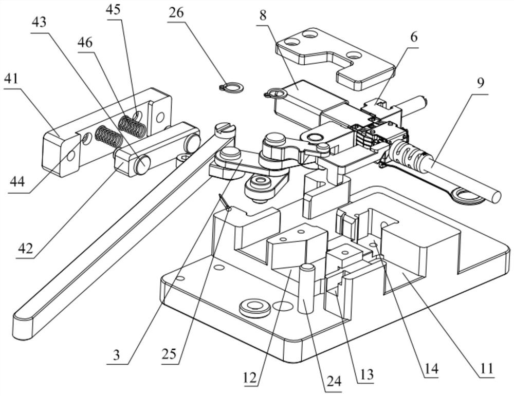
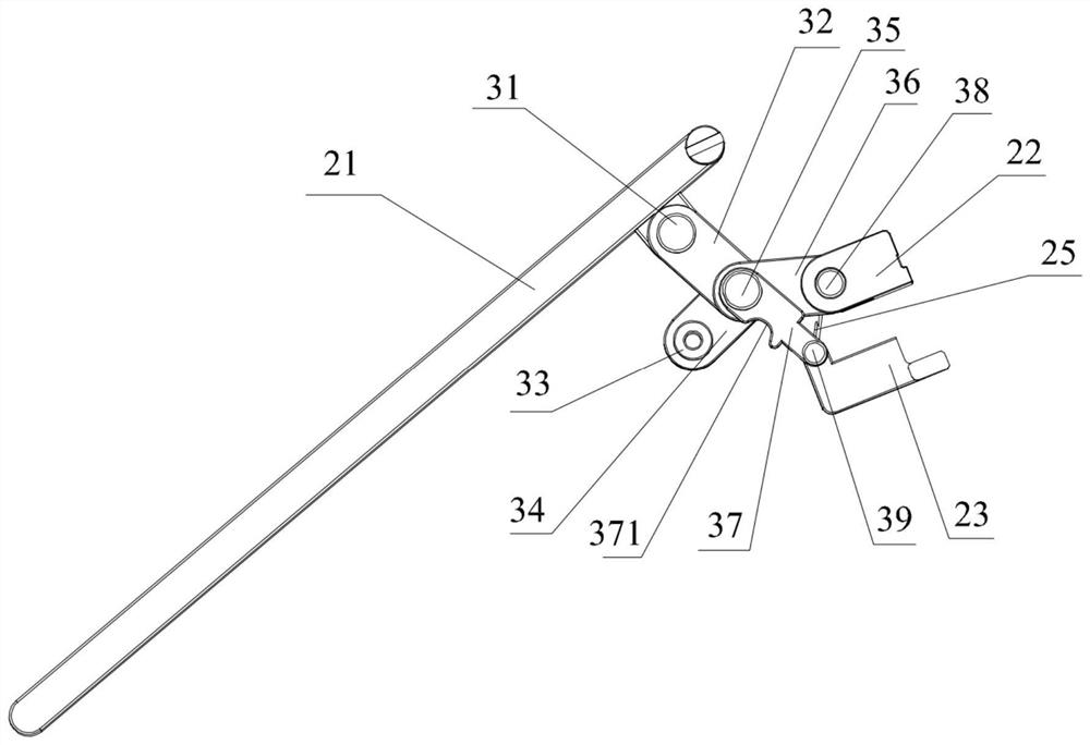
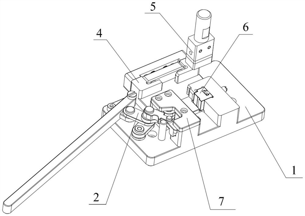
[0003] In view of the problems in the prior art that using a hand press to fix the lock spring is easy to cause the lock spring to be easily locked and misaligned, and the use of the hand press is often misplaced, the workload of the workers is increased, the labor cost is increased, and the efficiency is reduced. The present invention provides a The multi-link slider mechanism for the locking machine includes a handle, a multi-link control mechanism, a first slider for fastening the shrapnel, and a second slider for limiting the longitudinal position of the connector. The handle passes through The multi-link control mechanism controls the first slider and the second slider to lock the shrapnel and the connector

Method used


Image

  • Multi-connecting rod sliding block mechanism for locking machine
  • Multi-connecting rod sliding block mechanism for locking machine
  • Multi-connecting rod sliding block mechanism for locking machine

Examples


Embodiment Construction

[0045] In order to make the purpose, technical solutions and advantages of the embodiments of the present invention clearer, the technical solutions in the embodiments of the present invention will be clearly and completely described below in conjunction with the accompanying drawings in the embodiments of the present invention. Obviously, the described embodiments It is some embodiments of the present invention, but not all of them. Based on the implementation manners in the present invention, all other implementation manners obtained by persons of ordinary skill in the art without creative efforts fall within the protection scope of the present invention. Accordingly, the following detailed description of the embodiments of the invention provided in the accompanying drawings is not intended to limit the scope of the claimed invention, but merely represents selected embodiments of the invention. Based on the implementation manners in the present invention, all other implement...


PUM


Abstract

The invention discloses a multi-connecting rod sliding block mechanism for a locking machine, and belongs to the field of machinery. The multi-connecting rod sliding block mechanism comprises a handle, a multi-connecting rod control mechanism, a first sliding block for fastening an elastic sheet and a second sliding block for longitudinally limiting a connector, and the handle controls the first sliding block and the second sliding block to lock the elastic piece and the connector through the multi-connecting-rod control mechanism. The multi-connecting rod sliding block mechanism has the beneficial effects that the positions of the elastic piece and the connector are fixed through the first sliding block and the second sliding block in the sliding block mechanism, the placement position ofthe connector does not need to be manually adjusted in real time, locking deviation of the elastic piece does not occur, riveting can be fast and accurate, waste of human resources is avoided, and the loss caused by misoperation during product processing is reduced; and after a locking machine manufactured by the multi-connecting rod sliding block mechanism is debugged and used once, the lockingmachine can be repeatedly used by an operator without being debugged again, so that the production efficiency is improved, and the labor cost is reduced.

Description

technical field [0001] The invention relates to the mechanical field, in particular to a multi-link slider mechanism for a locking machine. Background technique [0002] A high-speed harness connector is an electronic component. The main function is to build a communication bridge between blocked or isolated circuits in the circuit, so that the circuit can be turned on, data transmission can be realized, and the circuit can realize the predetermined function. The high-speed wire harness connector needs to be fixed with the lock shrapnel during the production process. Usually, the worker places the high-speed wire harness connector and the shrapnel in a suitable position, operates the hand press, and then rives and fixes the wire harness connector and the lock shrapnel. Due to manual positioning, position determination and operation are prone to deviations, and the wire harness connector is prone to lock deviation when fixing the lock shrapnel, and it is often misplaced when...

Claims


Application Information

Patent Timeline
Patent Type & Authority Applications(China)
IPC IPC(8): H01R43/00H01R43/042H01R43/20B21D39/00B21D43/00
CPCH01R43/00H01R43/042H01R43/20B21D39/00B21D43/003
Inventor 林辉勇
Owner AMPHENOL (XIAMEN) HIGH SPEED CABLE CO LTD
Why Eureka
Try Eureka