Connector cover plate clamping and moving mechanism

A moving mechanism and connector technology, applied in the assembly/disassembly of contact parts, etc., can solve the problems of easy falling, cover falling off, slow speed, etc., and achieve the effects of smooth material removal, prevention of jamming, and prevention of pressure.

Inactive Publication Date: 2021-03-12
嘉兴晨翔智能装备有限公司
View PDF1 Cites 2 Cited by
  • Summary
  • Abstract
  • Description
  • Claims
  • Application Information

AI Technical Summary

Problems solved by technology

[0002] At present, the flexible flat cable of the connector needs to insert each core wire of the flexible flat cable into the corresponding U-shaped opening of the plastic groove, and then cover the entire groove with the cover plate to complete the assembly of the connector. The current cover plate The volume is small, and it is manually clamped and transported at a slow speed, and it is easy to drop during transport, which affects subsequent processing. Therefore, during production, it is necessary to use a more clamping device to clamp the cover plate, and then move to the processing Equipment, after the processing is completed, move the cover plate to the conveying equipment to effectively ensure production efficiency
[0003] The Chinese patent with the publication number CN103746256A discloses a clamping and moving mechanism for a connector cover plate, which has a simple structure, stable clamping movement, fast moving speed and high efficiency. However, its positioning When the pin is inserted and positioned, because the gap between the positioning pin and the positioning hole is small, when the cover plate is loosened, the cover plate is likely to cause poor fall-off, and when the equipment is clamped again, it is easy to cause stacking

Method used


Image

  • Connector cover plate clamping and moving mechanism
  • Connector cover plate clamping and moving mechanism
  • Connector cover plate clamping and moving mechanism

Examples


Embodiment Construction

[0024] The following will clearly and completely describe the technical solutions in the embodiments of the present invention with reference to the accompanying drawings in the embodiments of the present invention. Obviously, the described embodiments are only some, not all, embodiments of the present invention. Based on the embodiments of the present invention, all other embodiments obtained by persons of ordinary skill in the art without making creative efforts belong to the protection scope of the present invention.

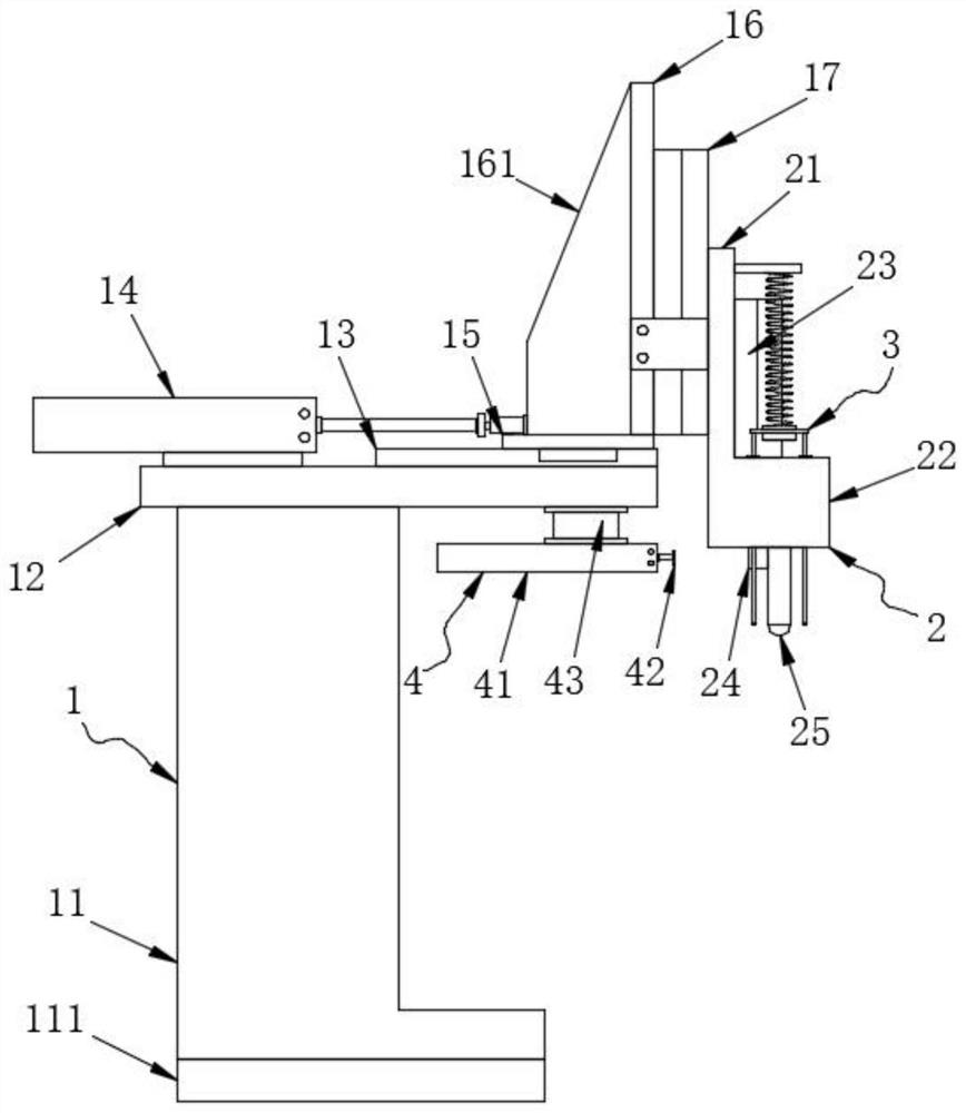
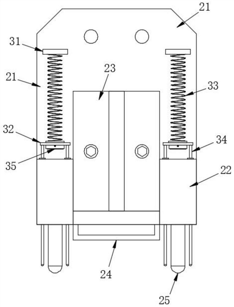
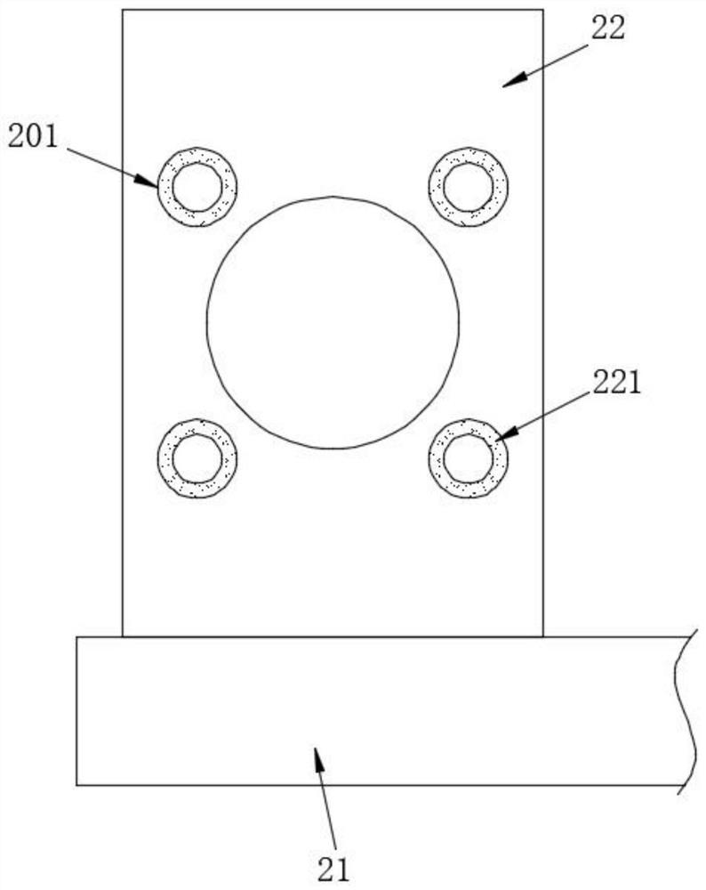
[0025] see Figure 1-4 , the present invention provides the following technical solutions: a connector cover clamping movement mechanism, including a support mechanism 1, the support mechanism 1 includes a support column 11 and a top plate 12 fixed on its top surface, and one side of the top surface of the top plate 12 is fixedly connected There is a first air cylinder 14, and the first air cylinder 14 is connected to the external air source. The top surface o...


PUM


Abstract

The invention belongs to the technical field of connector cover plate clamping devices, and particularly relates to a connector cover plate clamping and moving mechanism which comprises a supporting mechanism. The supporting mechanism comprises a supporting column and a top plate fixed to the top face of the supporting column, a first air cylinder is fixedly connected to one side of the top face of the top plate, and the first air cylinder is in transmission connection with an external air source. A guide rail is fixedly connected to the side, away from the first air cylinder, of the top surface of the top plate, and a sliding table is slidably connected to the guide rail. After machining is completed, the first air cylinder pushes the sliding table to slide forwards along the guide rail,a sliding table air cylinder on a mounting plate pushes the supporting plate to move downwards, and a second air cylinder drives a clamping jaw to loosen the cover plate; a sliding plate drives an ejector rod to slide downwards under the action of a spring so as to push away the cover plate, and meanwhile a patch vibration motor drives the sliding plate and the ejector rod to vibrate. Therefore, the cover plate can be better separated from a positioning pin, the phenomenon that the cover plate is clamped is effectively prevented, and the cover plate can be stripped more smoothly.

Description

technical field [0001] The invention belongs to the technical field of connector cover plate clamping equipment, and in particular relates to a connector cover plate clamping and moving mechanism. Background technique [0002] At present, the flexible flat cable of the connector needs to insert each core wire of the flexible flat cable into the corresponding U-shaped opening of the plastic groove, and then cover the entire groove with the cover plate to complete the assembly of the connector. The current cover plate The volume is small, and it is manually clamped and transported at a slow speed, and it is easy to drop during transport, which affects subsequent processing. Therefore, during production, it is necessary to use a more clamping device to clamp the cover plate, and then move to the processing Equipment, after the processing is completed, the cover plate is moved to the conveying equipment to effectively ensure production efficiency. [0003] The Chinese patent wi...

Claims


Application Information

Patent Timeline
Patent Type & Authority Applications(China)
IPC IPC(8): H01R43/20
CPCH01R43/20
Inventor 曹付刚
Owner 嘉兴晨翔智能装备有限公司
Why Eureka
Try Eureka