Nail taking device for orthopedics

An orthopedic, mid-position technology, applied in the direction of the fixator, can solve the problems of fracture site injury, low bone density of patients, and inability to flexibly adjust the nail removal device to achieve the effect of avoiding relative displacement

Active Publication Date: 2021-03-16
THE FIRST AFFILIATED HOSPITAL OF WANNAN MEDICAL COLLEGE YIJISHAN HOSPITAL OF WANNAN MEDICAL COLLEGE
View PDF11 Cites 1 Cited by
  • Summary
  • Abstract
  • Description
  • Claims
  • Application Information

AI Technical Summary

Problems solved by technology

[0003] At present, the common surgical nail removal method is to clamp the metal exposed part with forceps and rotate it forcefully to take out the steel nail. However, since there is no fixing device, once the doctor shakes his hands during the operation, the nail groove and the human body and the steel nail are easily damaged. The tissue of the fracture will cause re-injury to the fracture site, and because of the low bone density of some patients, it is difficult to form threads on the bone. When it is taken out, it cannot be screwed out after turning to a certain position, and it can only be idling on the spot. In the prior art, the nail-removing device also has a fixing device and an external setting threaded to cooperate to generate an outward pulling force and then remove the steel nail. However, when the fixing device is used, the whole device is first fixed on the hospital bed or the operating table. , and then take out the nails, but when taking out the bone nails in some parts, the nail taking device with a fixed setting cannot be adjusted flexibly, and there is some inconvenience, for example, the angle of the steel nail insertion

Method used


Image

  • Nail taking device for orthopedics
  • Nail taking device for orthopedics
  • Nail taking device for orthopedics

Examples


Embodiment Construction

[0020] The following will clearly and completely describe the technical solutions in the embodiments of the present invention with reference to the accompanying drawings in the embodiments of the present invention. Obviously, the described embodiments are only some, not all, embodiments of the present invention. Based on the embodiments of the present invention, all other embodiments obtained by persons of ordinary skill in the art without making creative efforts belong to the protection scope of the present invention.

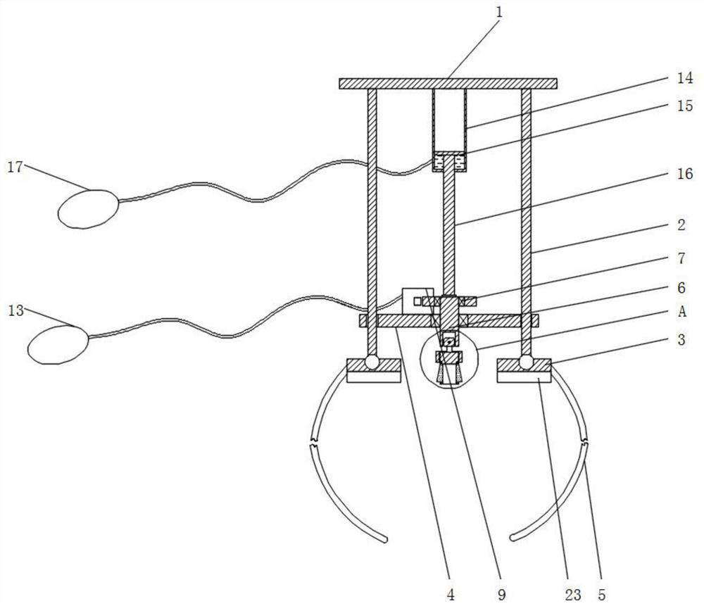
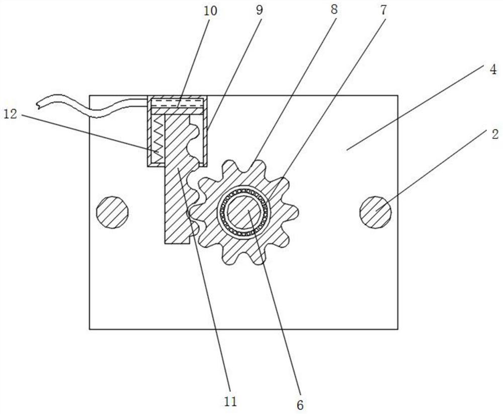
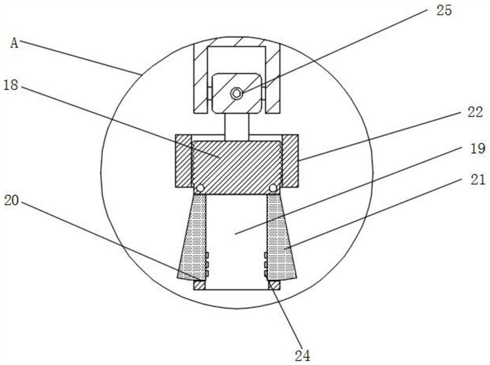
[0021] see Figure 1-3 , an embodiment provided by the present invention: a nail removal device for orthopedics, including a positioning unit and a nail removal unit, the positioning unit includes a top plate 1, a slide bar 2 vertically arranged at both ends of the bottom of the top plate 1, and hingedly arranged on the slide bar 2 The bottom collision block 3 and the sliding plate 4 are arranged between the two slide bars 2, the two collision blocks 3 are pro...


PUM


Abstract

The invention discloses a nail taking device for orthopedics. The nail taking device comprises a positioning unit and a nail taking unit, wherein the positioning unit comprises a top plate, sliding rods vertically arranged at the two ends of the bottom of the top plate, abutting blocks arranged at the bottoms of the sliding rods in a hinged mode, a moving plate arranged between the two sliding rods in a sliding mode and fixing belts arranged on the opposite sides of the two abutting blocks. For a patient with relatively low bone density, a doctor can repeatedly press a pressing bag I with onehand to enable a rotating rod to rotate constantly, and can press a pressing bag II with the other hand to enable hydraulic oil in the pressing bag II to enter a piston cylinder II through a hose, a piston II moves upwards in a piston cylinder I, and a connecting rod is driven to move upwards, so that the connecting rod generates certain tension on the rotating rod to be matched with the rotatingrod to take out a steel nail; and for a patient with relatively high bone density, the doctor only needs to repeatedly press the pressing bag I, a thread is formed on the bone, and therefore, the steel nail is enabled to be automatically moved out.

Description

technical field [0001] The invention relates to the technical field of nail removal devices, in particular to a nail removal device for orthopedics. Background technique [0002] In clinical medicine, fracture is one of the common diseases of bone trauma. The method often used to treat fractures is to implement internal fixation surgery, that is, after the fracture site is reset, the bone plate and screws made of metal materials are used to connect the reset bones. However, in the process of removing the bone plate after internal fixation surgery, the screws need to be removed. [0003] At present, the common method of surgical nail removal is to clamp the metal exposed part with forceps and rotate it to remove the steel nail. However, since there is no fixing device, once the doctor shakes his hand during the operation, the nail groove and the human body are easily damaged. The tissue of the fracture will cause re-injury to the fracture site, and because of the low bone de...

Claims


Application Information

Patent Timeline
Patent Type & Authority Applications(China)
IPC IPC(8): A61B17/92
CPCA61B17/92
Inventor 汪正宇韦山杨民胡旭峰陶周善周运峰
Owner THE FIRST AFFILIATED HOSPITAL OF WANNAN MEDICAL COLLEGE YIJISHAN HOSPITAL OF WANNAN MEDICAL COLLEGE
Why Eureka
Try Eureka