
Waste box for collecting metal chips

A technology for metal chips and waste bins, which is used in metal processing equipment, metal processing machinery parts, maintenance and safety accessories, etc., can solve problems such as non-compliance with emission standards, and achieve the effect of meeting emission standards

Inactive Publication Date: 2021-03-16
咸宁新创工业设计有限公司
View PDF4 Cites 0 Cited by
  • Summary
  • Abstract
  • Description
  • Claims
  • Application Information

AI Technical Summary

Problems solved by technology

[0002] The metal material is produced on the cutting equipment to produce metal chips, and the cutting wheel of the cutting equipment needs to be cooled during the cutting process. Generally, the cutting fluid is used to cool down and lubricate the cutting wheel; thus the metal chips will be mixed with the chips after use. In the cutting fluid, the metal chips mixed in it need to be filtered when the cutting fluid is recycled and used. At present, a waste box with a filter screen or a filter hole is generally used to filter and block the metal chips. There is a waste box with a filter hole at the bottom. The cutting fluid can be discharged from the filter hole. When the waste box is full of metal chips, the chips need to be dumped, but the dumped metal chips will still be accompanied by cutting fluid, which does not meet the discharge standard, so a kind of cutting fluid is required. Dispose of clean waste bins

Method used


Image

  • Waste box for collecting metal chips
  • Waste box for collecting metal chips
  • Waste box for collecting metal chips

Examples


Embodiment Construction

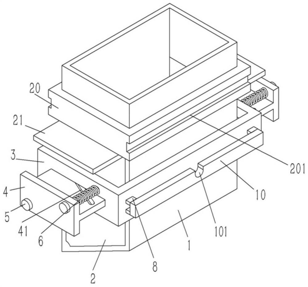
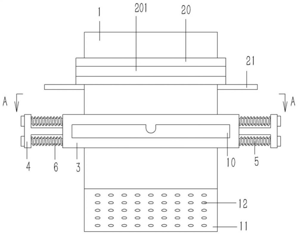
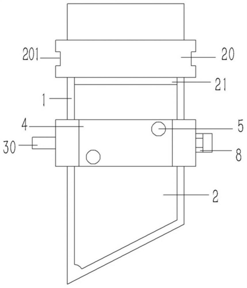
[0020] Example: see Figures 1 to 4 As shown, a waste box for collecting metal chips includes a rectangular box body 1. The lower end of the box body 1 is formed with a slanted bottom 11, and several water filter holes 12 are formed on the slanted bottom 11. The left and right sides of the box body 1 are opposite to each other. A splint 2 is plugged into the side wall, and the upper end of the splint 2 is bent to form a horizontal baffle plate 21, which is distributed on both sides of the box body 1; Support frame 3, there is a gap between the left and right frames of the lower support frame 3 and the left and right side walls of the box body 1; the left and right frames of the lower support frame 3 are plugged with a T-shaped drive plate 4, The inner side of the drive plate 4 is fixed on the splint 2, the drive plate 4 is composed of a horizontal part and a vertical part, an inclined guide groove 41 is formed on the horizontal part of the drive plate 4, and a guide groove 41 ...


PUM


Abstract

The invention discloses a waste box for collecting metal chips. The waste box comprises a rectangular box body, wherein clamping plates are inserted into the two side walls of the box body, the upperends of the clamping plates are each bent to form a horizontal baffle plate, a rectangular lower supporting frame is inserted and fixed on the box body, and gaps are formed between left and right frames of the lower supporting frame and the side walls of the box body. T-shaped driving plates are inserted into the left and right frames of the lower supporting frame, the inner side edges of the driving plates are fixed to the clamping plates, each driving plate is composed of a horizontal part and a vertical part, inclined guide grooves are formed in the horizontal parts of the driving plates, vertical guide shafts are inserted into the guide grooves, the two ends of each guide shaft penetrate through driving rods and are hinged to guide wheels through bearings, the guide wheels abut againstthe inner walls of the left side and the right side of the lower supporting frame, and the driving rods are parallel to the left side wall and the right side wall of the box body and penetrate through the lower supporting frame to be fixed with pull rods.

Description

technical field [0001] The invention relates to the technical field of metal cutting devices, in particular to a waste box for collecting metal chips. Background technique [0002] The metal material is produced on the cutting equipment to produce metal chips, and the cutting wheel of the cutting equipment needs to be cooled during the cutting process. Generally, the cutting fluid is used to cool down and lubricate the cutting wheel; thus the metal chips will be mixed with the chips after use. In the cutting fluid, the metal chips mixed in it need to be filtered when the cutting fluid is recycled and used. At present, a waste box with a filter screen or a filter hole is generally used to filter and block the metal chips. There is a waste box with a filter hole at the bottom. The cutting fluid can be discharged from the filter hole. When the waste box is full of metal chips, the chips need to be dumped, but the dumped metal chips will still be accompanied by cutting fluid, wh...

Claims


Application Information

Patent Timeline
Patent Type & Authority Applications(China)
IPC IPC(8): B23Q11/00B23Q11/10
CPCB23Q11/00B23Q11/1069
Inventor 徐芳蕾
Owner 咸宁新创工业设计有限公司
Learn More