
An electrical system for an exoskeleton robot

An exoskeleton robot and electrical system technology, applied in manipulators, program-controlled manipulators, manufacturing tools, etc., can solve the problems of large number of wiring harnesses, complex mechanisms, increased time costs and personnel costs, etc., to reduce system complexity and improve System stability and cost reduction effects

Active Publication Date: 2022-04-19
MEBOTX INTELLIGENT TECH SUZHOU CO LTD
View PDF7 Cites 0 Cited by
  • Summary
  • Abstract
  • Description
  • Claims
  • Application Information

AI Technical Summary

Problems solved by technology

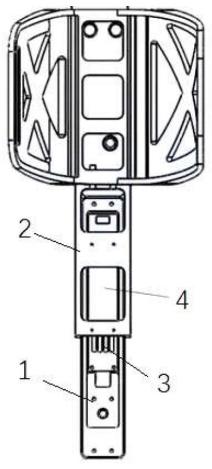
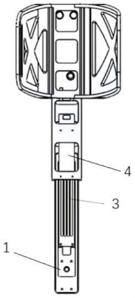
[0003] The applicant found in practical applications that the existing active lower limb weight-assisted exoskeleton robots need to use a lot of sensors when judging the human body posture and motion state, including the attitude reference system for measuring the attitude angle and acceleration, and the joint angle measurement system. Encoders or potentiometers, pressure sensors for measuring human-computer interaction force, etc., the mechanism for installing these sensors is relatively complicated and the number of wiring harnesses connecting each sensor and the main control unit is large
On the one hand, this increases the volume and weight of the exoskeleton robot, which affects the wearing comfort. On the other hand, it significantly increases the complexity of the installation, commissioning and post-maintenance of the exoskeleton robot, and increases the time cost and personnel in the production process of the exoskeleton robot. Cost, it is not easy to industrialize the development of exoskeleton robots

Method used


Image

  • An electrical system for an exoskeleton robot
  • An electrical system for an exoskeleton robot
  • An electrical system for an exoskeleton robot

Examples


Embodiment Construction

[0031] In order to make the purpose and technical solutions of the embodiments of the present invention more clear, the technical solutions of the embodiments of the present invention will be clearly and completely described below in conjunction with the drawings of the embodiments of the present invention. Apparently, the described embodiments are some, not all, embodiments of the present invention. Based on the described embodiments of the present invention, all other embodiments obtained by persons of ordinary skill in the art without creative efforts shall fall within the protection scope of the present invention.

[0032] Those skilled in the art can understand that, unless otherwise defined, all terms (including technical and scientific terms) used herein have the same meaning as commonly understood by one of ordinary skill in the art to which this invention belongs. It should also be understood that terms such as those defined in commonly used dictionaries should be und...


PUM


Abstract

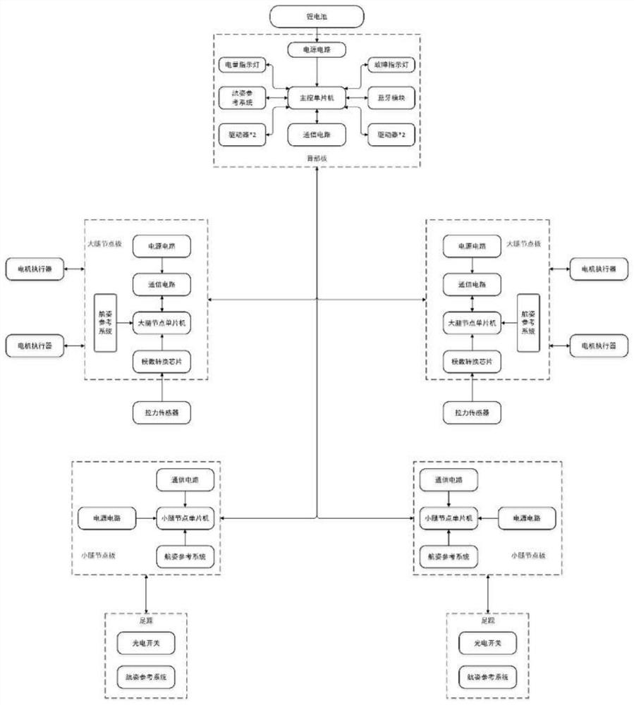
The invention belongs to the field of exoskeleton robots, and relates to an electrical system of an exoskeleton robot, comprising: a power supply unit for supplying power to the entire electrical system; a main control unit for controlling each unit; a drive unit for driving the hip joint of the exoskeleton Exercise, and drive the knee joint movement through steel rope traction; the sensing unit includes the back attitude reference system set on the back, the thigh attitude reference system set on the thigh, the calf attitude reference system set on the calf, and the thigh attitude reference system set on the thigh The steel rope tension sensor, the foot attitude reference system on the foot, and the foot reflective infrared photoelectric switch sensor on the foot; among them, the way to determine the zero point of the hip joint angle is through the back attitude reference system and the thigh navigation system. Calculate the pitch angle difference of the attitude reference system to calculate the zero point position of the hip joint angle. The electrical system of the present application can reduce the volume and weight of the exoskeleton robot while ensuring the normal acquisition of human body posture data.

Description

technical field [0001] The invention belongs to the field of exoskeleton robots and relates to an electrical system of an exoskeleton robot. Background technique [0002] The lower limb weight-assisted exoskeleton robot is mainly provided for normal people to wear, which is used to enhance the individual's strength, endurance and other physical capabilities, so that the wearer's sense of weight is significantly reduced. People wear such exoskeletons to lift heavy objects, carry heavy objects over long distances and work with heavy tools. It is mainly used in the military field where soldiers carry heavy weapons and improves their combat capabilities; at the same time, it is also used in emergency rescue and disaster relief, assisting officers and soldiers to quickly deliver rescue items to the scene in civilian fields, and industrial industries that relieve workers' fatigue caused by long hours of high-intensity work. field. [0003] The applicant found in practical applic...

Claims


Application Information

Patent Timeline
Patent Type & Authority Patents(China)
IPC IPC(8): B25J9/00B25J9/10B25J9/12
CPCB25J9/0006B25J9/12B25J9/104
Inventor 魏巍林西川夏禹轩
Owner MEBOTX INTELLIGENT TECH SUZHOU CO LTD
Learn More