Energy-saving mobile charging station

A charging station and mobile technology, applied in the field of energy-saving mobile charging stations, can solve the problems of resource waste and unavailability, and achieve the effect of saving electric energy and avoiding resource waste.

Inactive Publication Date: 2021-03-16
ANHUI USEM TECH CO LTD
View PDF8 Cites 1 Cited by
  • Summary
  • Abstract
  • Description
  • Claims
  • Application Information

AI Technical Summary

Problems solved by technology

[0003] The mobile charging station is a kind of charging station, but the traditional mobile charging station will produce bumps during the moving process, and a relative displacement will occur. This displacement will do work, which cannot be used, resulting in waste of resources. In summary, this application now proposes an energy-saving mobile charging station to solve the above-mentioned problems

Method used


Image

  • Energy-saving mobile charging station
  • Energy-saving mobile charging station
  • Energy-saving mobile charging station

Examples


Embodiment 1

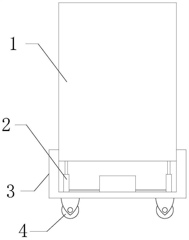
[0024] see Figure 1-Figure 4 , an energy-saving mobile charging station, comprising a charging station body 1, a base 3 and a universal wheel 4, the charging station body 1 is located on the base 3, and the universal wheel 4 is rotatably connected to the bottom of the base 3; including an energy-saving mechanism 2. The energy saving mechanism 2 is located between the base 3 and the charging station body 1 .

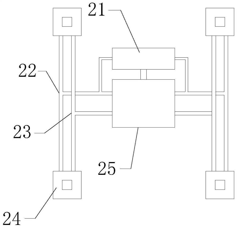
[0025] As an improvement of the above solution, the energy-saving mechanism 2 includes a power cylinder 24 and a generator 21 , the power cylinder 24 is arranged between the base 3 and the charging station body 1 , and the fixing part of the power cylinder 24 is fixed on the base 3 , and the telescopic part of the power cylinder 24 is fixedly connected with the charging station body 1, the oil inlet 254 of the generator 21 is connected with the oil outlet of the power cylinder 24 through the oil inlet pipeline 23, and the oil outlet of the generator 21 is connected It i...

Embodiment 2

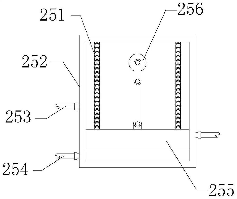
[0029] see image 3 , as an improvement of the above scheme, the energy-saving mechanism 2 also includes a voltage-stabilizing assembly 25, the voltage-stabilizing assembly 25 includes a voltage-stabilizing chamber 252, a piston plate 255 and a spring 21, and the bottom of the voltage-stabilizing chamber 252 is connected with an oil inlet Port 254, the pressure chamber 252 is connected with an oil outlet, and the oil outlet is opened later than the oil inlet 254, and the oil inlet 254 is connected with the oil inlet pipeline 23, and the oil outlet is connected with the oil inlet of the generator 21. The port 254 is connected, the piston plate 255 is slidably connected to the inner wall of the surge chamber 252, and the surge chamber 252 is divided into two mutually sealed cavities, and the piston plate 255 is connected to the surge chamber 252 through the spring 21. .

[0030] As an improvement of the above solution, both the oil inlet 254 and the oil outlet are provided with...

Embodiment 3

[0033] see Figure 4 , as an improvement of the above scheme, the voltage stabilization component 25 includes an auxiliary voltage stabilization structure 256, and the auxiliary voltage stabilization structure 256 includes a rotating shaft 2561, a torsion spring 2564, a first connecting rod 2562 and a second connecting rod 2563. The rotating shaft 2561 is rotatably connected inside the pressure-stabilizing chamber 252, the torsion spring 2564 is sleeved outside the rotating shaft 2561, and is fixed inside the pressure-stabilizing chamber 252, one end of the first connecting rod 2562 is fixedly connected with the rotating shaft 2561, and the first connecting rod 2562 is fixedly connected to the rotating shaft 2561. One end of the second connecting rod 2563 is rotatably connected with the other end of the first connecting rod 2562 , and the second connecting rod 2563 is rotatably connected to the piston plate 255 .

[0034] Working process: when the piston plate 255 moves upward...


PUM


Abstract

The invention provides an energy-saving mobile charging station which comprises a charging station body and a base. The charging station body is located on the base; an energy-saving mechanism is included, the energy-saving mechanism is located between the base and the charging station body, the energy-saving mechanism comprises a power oil cylinder and an electric generator, the power oil cylinder is arranged between the base and the charging station body, a fixing part of the power oil cylinder is fixed to the base, and a telescopic part of the power oil cylinder is fixedly connected with the charging station body; and an oil inlet of the electric generator is connected with an oil outlet of the power oil cylinder through an oil inlet pipeline, and the oil outlet of the electric generator is connected with the oil inlet of the power oil cylinder through an oil outlet pipeline. Oil pressure is increased, the electric generator generates electricity, electric energy is saved, resourcewaste is avoided, oil enters the electric generator in a high-pressure state, the generator continuously generates electricity, and problems that an electricity generation process is interrupted and electricity generation efficiency is low due to the fact that the oil pressure is too low are solved.

Description

technical field [0001] One or more embodiments of this specification relate to the field of charging station equipment, and in particular, to an energy-saving mobile charging station. Background technique [0002] The function of the charging pile is similar to the refueling machine in the gas station. It can be fixed on the ground or wall and installed in public buildings (public buildings, shopping malls, public parking lots, etc.) and residential parking lots or charging stations. Charge various models of electric vehicles. The input end of the charging pile is directly connected to the AC power grid, and the output end is equipped with a charging plug for charging the electric vehicle. Charging piles generally provide two charging methods: conventional charging and fast charging. People can use a specific charging card to swipe the card on the human-computer interaction interface provided by the charging pile to perform operations such as corresponding charging methods,...

Claims


Application Information

Patent Timeline
Patent Type & Authority Applications(China)
IPC IPC(8): B60L53/30B60L53/57F03C1/02
CPCB60L53/30B60L53/57F03C1/02Y02T10/70Y02T10/7072Y02T90/12
Inventor 桂吉祥吴旭红陆继文石伟张磊
Owner ANHUI USEM TECH CO LTD
Why Eureka
Try Eureka