
Cleaning equipment for photovoltaic panels

A technology for cleaning equipment and photovoltaic panels, which can be applied to cleaning methods using liquids, cleaning methods using tools, mechanical equipment, etc., and can solve problems such as unfavorable photovoltaic panels absorbing solar energy, large dust and soil, and low efficiency.

Active Publication Date: 2022-06-28
浙江蓝特新能源科技股份有限公司
View PDF0 Cites 0 Cited by
  • Summary
  • Abstract
  • Description
  • Claims
  • Application Information

AI Technical Summary

Problems solved by technology

[0002] With the gradual advancement of the country's new energy strategy, the current solar or photovoltaic industry is gradually expanding. Photovoltaic panels have a lot of room for development in the vast, flat and sunny areas. Photovoltaic street lights are installed on both sides of the existing roads. The panels absorb solar energy, and the solar energy is converted into electrical energy to supply power to the street lamps. However, these photovoltaic street lamps also have a disadvantage, that is, the dust on the road is relatively large, and the dust falling on the photovoltaic panels is not conducive to the photovoltaic panels absorbing solar energy, so it needs to be timed. For cleaning, the current cleaning work is manually operated, and the cleaning personnel are lifted to the side of the photovoltaic panels for cleaning by elevators. Manual operation leads to relatively low efficiency. For a large number of photovoltaic panels, automated cleaning equipment is urgently needed

Method used


Image

  • Cleaning equipment for photovoltaic panels
  • Cleaning equipment for photovoltaic panels
  • Cleaning equipment for photovoltaic panels

Examples


Embodiment

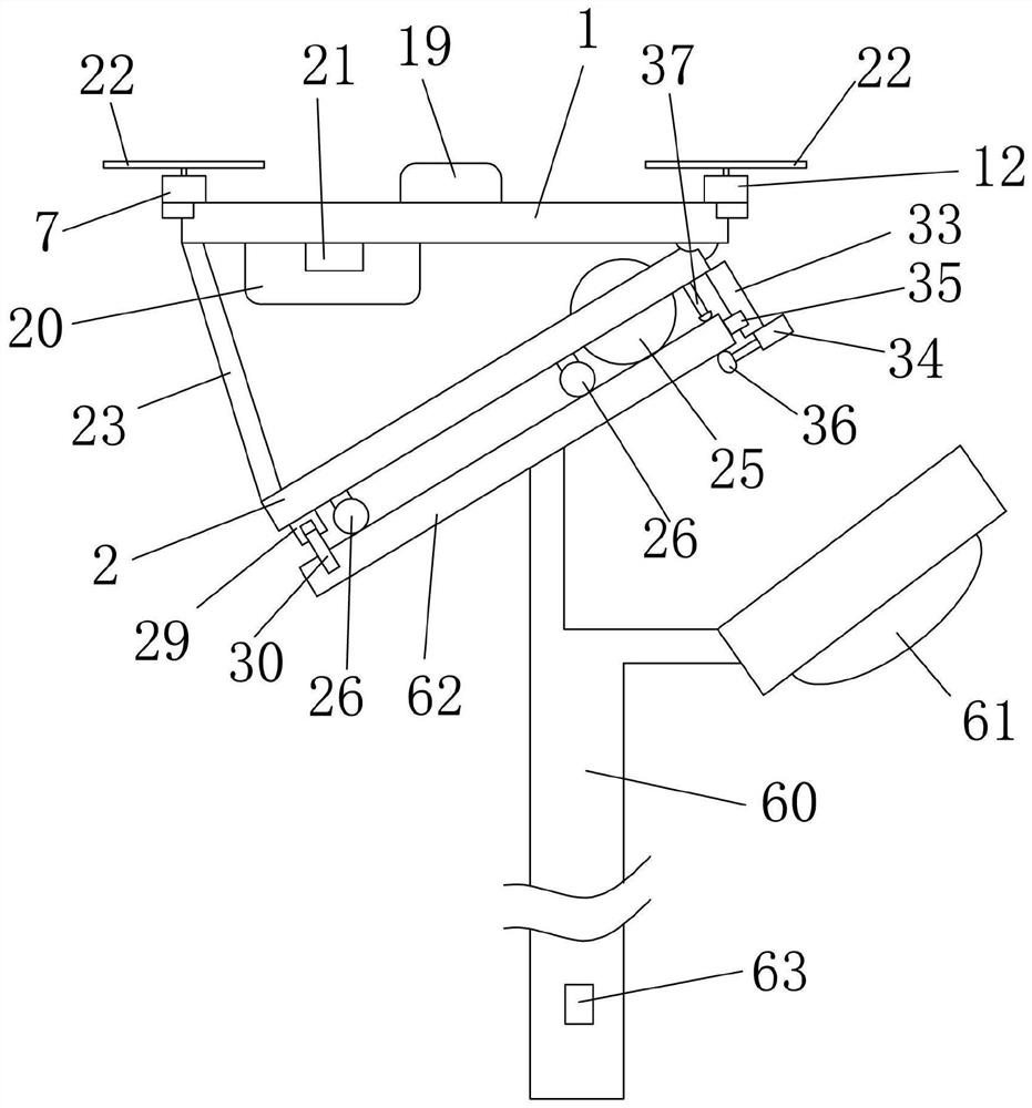
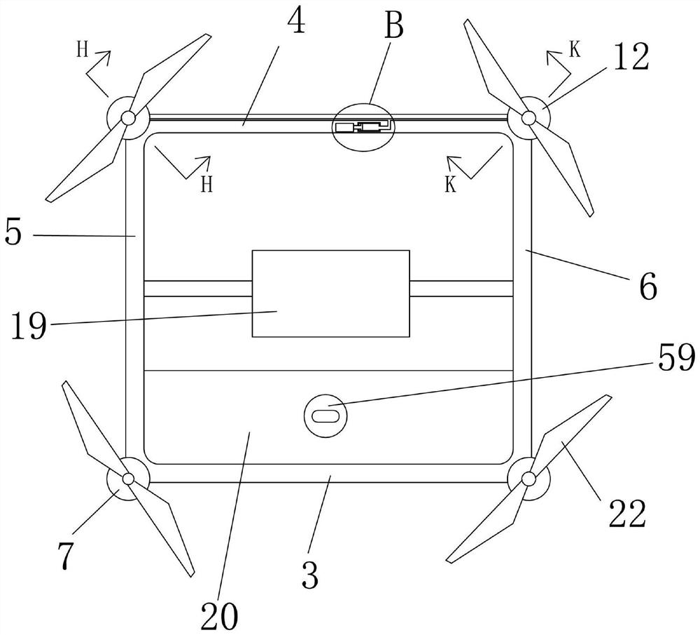
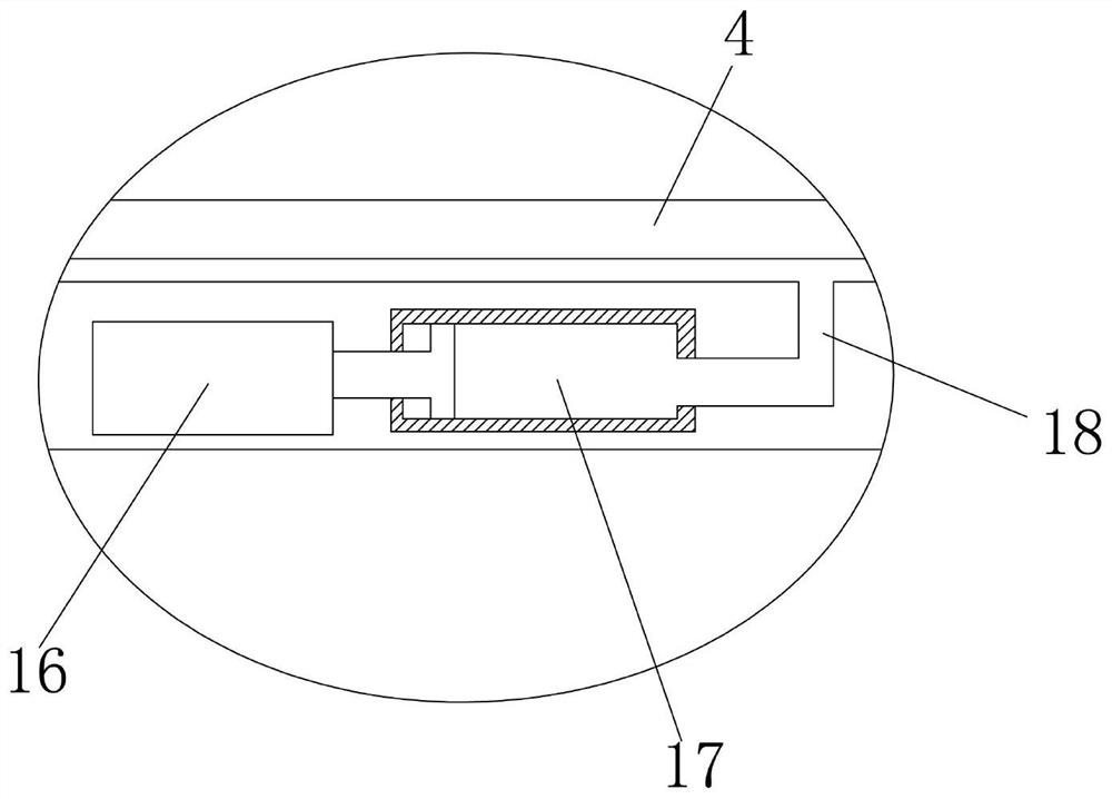
[0028] Example: a cleaning device for photovoltaic panels, such as Figure 1-Figure 13 As shown, it includes a flight frame and a cleaning frame, the flight frame is set horizontally, the flight frame includes a front frame, a rear frame, a left frame and a right frame, and the left end of the front frame is It is fixedly connected to the front end of the left frame, the right end of the front frame is fixedly connected to the front end of the right frame, the left end of the rear frame is fixedly connected to the rear end of the left frame, and the right end of the rear frame is fixedly connected to the rear end of the right frame Fixed connection, the upper sides of the left and right ends of the front frame are provided with front flight motors, the upper side of the left end of the rear frame is provided with a left support plate, and the upper side of the right end of the rear frame is provided with a right support plate, The upper surfaces of the left support plate and t...


PUM


Abstract

A photovoltaic panel cleaning device, belonging to the technical field of photovoltaic panel cleaning equipment; the left conductive rod is in contact with the left conductive strip, and the right conductive rod is in contact with the right conductive strip, so as to realize the effect of charging the lithium battery module when the present invention works, The on-site working life time of the present invention is improved; the clamping electric cylinder extends the piston rod, so that the clamping wheel is positioned on the lower side of the photovoltaic panel, and the stable effect of the present invention is obtained during operation, and the left electric cylinder and the right electric cylinder control the expansion and contraction of the splint , the splints on both sides clamp the photovoltaic panel, so that the front end of the cleaning rack is firmly above the front end of the photovoltaic panel; the first drive motor drives the brush reel, the second drive motor drives the main drive wheel, and the rotation of the transmission belt drives the connecting rod , the rotation of the connecting rod makes the rotating shaft wheel pull the rotating shaft to realize the cleaning roller moving back and forth in the cleaning port; the Velcro mother surface and the Velcro sub surface are set to realize the effect of easy replacement of the brush roll, and the brushes of different materials or specifications can be replaced.

Description

technical field [0001] The invention belongs to the technical field of photovoltaic panel cleaning equipment, and particularly relates to a photovoltaic panel cleaning equipment. Background technique [0002] With the gradual advancement of the country's new energy strategy, the solar or photovoltaic industry is gradually expanding. Photovoltaic panels have a lot of room for development in vast, flat and sunny areas. Photovoltaic street lights are installed on both sides of the existing roads. The panels absorb solar energy, and the solar energy is converted into electrical energy to supply power to the street lamps. However, these photovoltaic street lamps also have a disadvantage, that is, the dust on the road is relatively large, and the dust falling on the photovoltaic panels is not conducive to the photovoltaic panels to absorb solar energy, so it needs to be timed. For cleaning, the current cleaning work is manually operated. The cleaning personnel are raised to the si...

Claims


Application Information

Patent Timeline
Patent Type & Authority Patents(China)
IPC IPC(8): B64C39/02B64D27/24H02S40/10B08B3/02B08B1/04F21S9/03F21V23/00F21W131/103
CPCB64C39/024B64D27/24H02S40/10B08B3/02F21S9/03F21V23/02F21W2131/103B08B1/32B08B1/12Y02T50/60Y02E10/50Y02B20/72
Inventor 周汉军兰尚彬
Owner 浙江蓝特新能源科技股份有限公司
Learn More