
Charging wire positioning and fixing device for new energy automobile

A technology of new energy vehicles and fixtures, applied in the direction of electric vehicle charging technology, charging stations, electric vehicles, etc., can solve problems such as inability to adjust, and achieve the effect of ensuring cleanliness

Inactive Publication Date: 2021-03-16
岳翠娥
View PDF1 Cites 0 Cited by
  • Summary
  • Abstract
  • Description
  • Claims
  • Application Information

AI Technical Summary

Problems solved by technology

The new energy electric vehicle charging cable fixing device in the above-mentioned patent has the following disadvantages: the charging cable is placed in the bracket for support, and the bracket can only be stretched in a straight line, and cannot be adjusted according to the charging pile and the vehicle, and cannot meet the needs of use

Method used

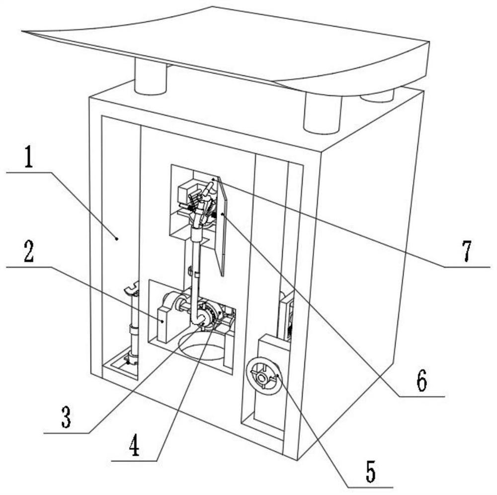
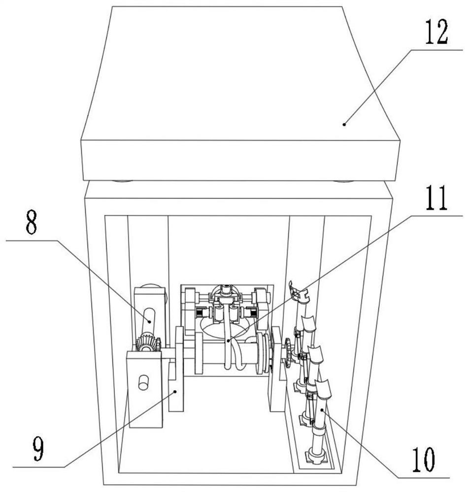
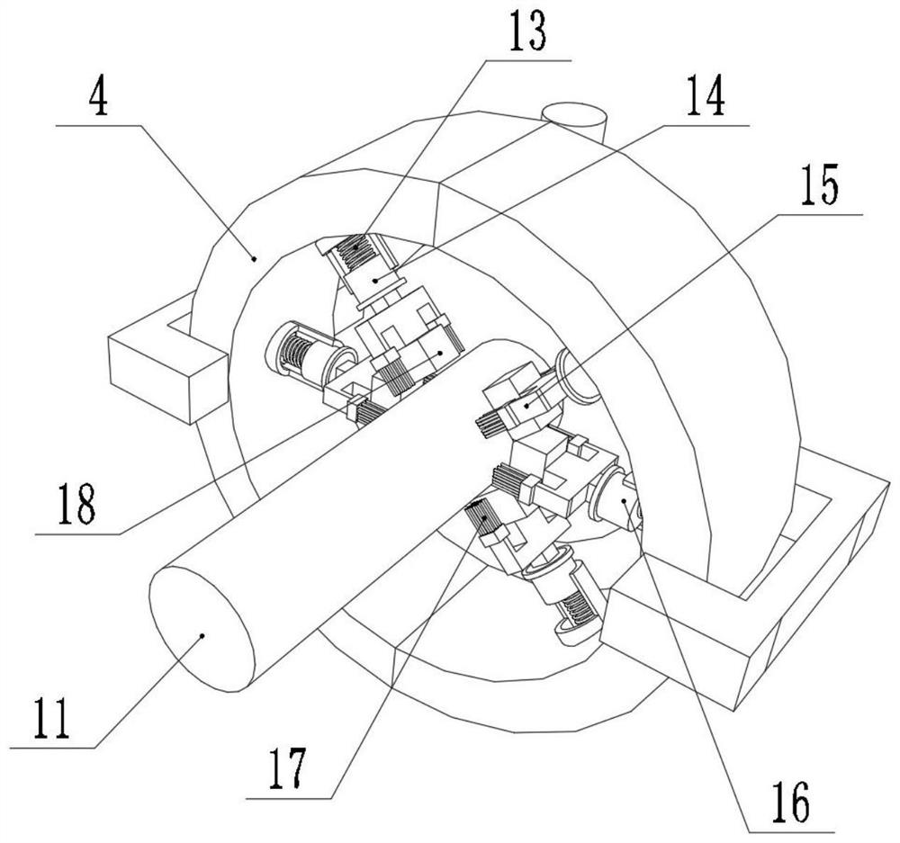

Image

  • Charging wire positioning and fixing device for new energy automobile
  • Charging wire positioning and fixing device for new energy automobile
  • Charging wire positioning and fixing device for new energy automobile

Examples


Embodiment Construction

[0028] The technical solution of this patent will be further described in detail below in conjunction with specific embodiments.

[0029] Embodiments of the present patent are described in detail below, examples of which are shown in the drawings, wherein the same or similar reference numerals designate the same or similar elements or elements having the same or similar functions throughout. The embodiments described below by referring to the figures are exemplary and are only used for explaining the patent, and should not be construed as limiting the patent.

[0030] In the description of this patent, it is to be understood that the terms "center", "upper", "lower", "front", "rear", "left", "right", "vertical", "horizontal", The orientation or positional relationship indicated by "top", "bottom", "inner", "outer", etc. is based on the orientation or positional relationship shown in the drawings, and is only for the convenience of describing this patent and simplifying the des...


PUM


Abstract

The invention discloses a charging wire positioning and fixing device for a new energy automobile, and relates to the technical field of new energy automobiles. The problem that the placing angle of acharging wire cannot be adjusted is solved. The device specifically comprises a shell and a power transmission line protection shell, wherein a supporting mechanism is placed on the inner wall of oneside of the shell, the supporting mechanism comprises two or more supporting rods, a contraction assembly and a fixing assembly, the outer walls of the supporting rods are rotationally connected withrotating sleeves, universal wheels are arranged on the two sides of the bottoms of the supporting rods, and the contraction assembly is composed of two connecting columns, four connecting plates andtwo connecting frames. According to the device, the supporting mechanism is arranged and used for supporting the power transmission line protection shell, during use, the supporting mechanism is takenout, then the supporting rods are pulled, so that the contraction assembly is deformed, and the distance between the two supporting rods is increased; and in order to adjust the direction, the rotating sleeves on the supporting rods can rotate, at the moment, the supporting rods are rotated, the angle of each supporting rod can be adjusted, and the device can meet different requirements.

Description

technical field [0001] The invention relates to the technical field of new energy vehicles, in particular to a charging line positioning and fixing device for new energy vehicles. Background technique [0002] With the progress of society and the rapid development of new energy vehicles, the demand for electric vehicle charging piles continues to increase. Charging piles are equipped with long charging lines to charge electric vehicles. Manually dragging the charging cable for storage, hanging or laying on the ground at will is prone to knotting of the charging cable, friction with the ground and damage, and the hanging and pulling process is time-consuming and laborious. [0003] After searching, the Chinese patent application number is 201710355289.2, which discloses a new energy electric vehicle charging line fixing device, including a fixed base fixed on the ground at the lower end of the charging pile. The two ends of the fixed base are respectively provided with inclin...

Claims


Application Information

Patent Timeline
IPC IPC(8): B65H75/44B65H75/38B08B1/00B60L53/18
CPCB65H75/4402B65H75/38B60L53/18B65H2701/34B08B1/12Y02T10/70Y02T10/7072Y02T90/14
Inventor 岳翠娥
Owner 岳翠娥
Learn More