
Polarization unrelated high speed photo switch

A high-speed optical switch and polarization technology, applied in the field of optical switches, can solve the problems of large size and high driving voltage, and achieve the effects of fast speed, fast response speed and increased response bandwidth

Inactive Publication Date: 2007-04-04
SHANGHAI INST OF OPTICS & FINE MECHANICS CHINESE ACAD OF SCI
View PDF4 Cites 0 Cited by
  • Summary
  • Abstract
  • Description
  • Claims
  • Application Information

AI Technical Summary

Problems solved by technology

This type of switch is characterized by a step function between the output intensity of the light and the input voltage, so it has the advantages of low precision requirements for driving voltage control, simple structure, and polarization insensitivity, but this type of switch also has obvious disadvantages. , such as high driving voltage, large size, etc.

Method used


Image

  • Polarization unrelated high speed photo switch
  • Polarization unrelated high speed photo switch
  • Polarization unrelated high speed photo switch

Examples


Embodiment Construction

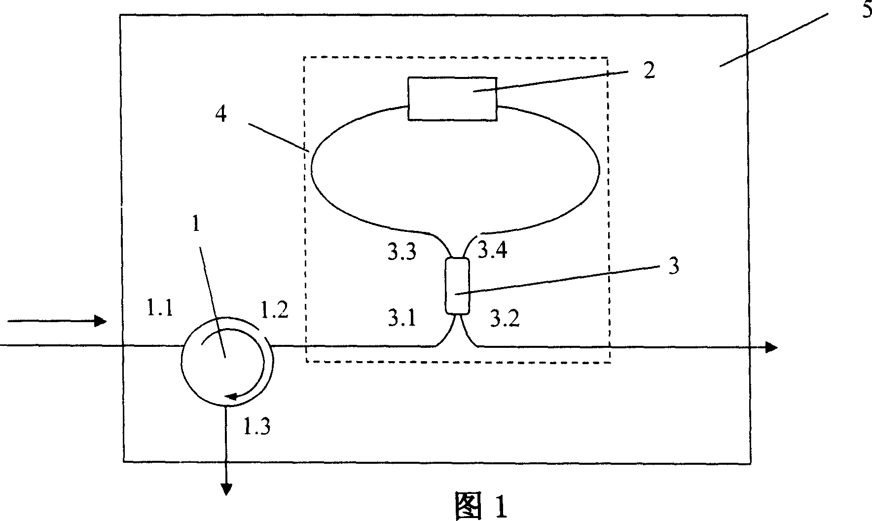
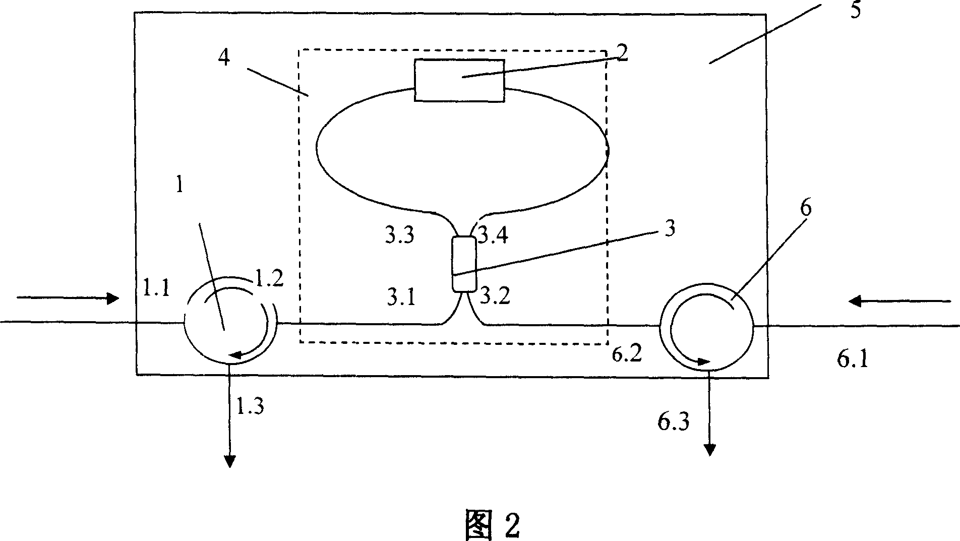
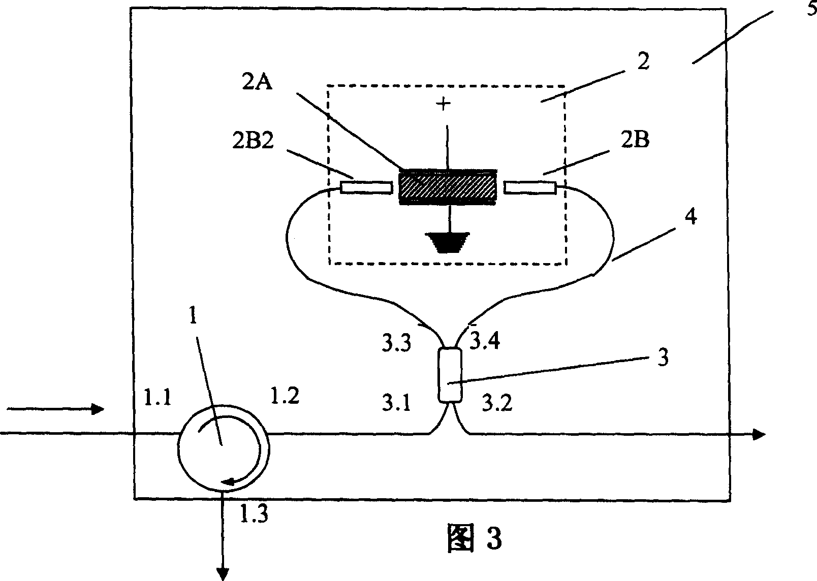
[0028] Please refer to FIG. 1 first. FIG. 1 is a schematic diagram of embodiment 1 of the present invention-a polarization-independent high-speed optical switch. As can be seen from the figure, the composition of the polarization-independent high-speed optical switch of the present invention is: a third port 3.3 and a fourth port 3.4 on the same side of a coupler 3 are connected to form a ring mirror 4, and a polarization control device 2 is connected in series in the ring mirror 4 , constitute the driving device of the switch, the first port 3.1 of the coupler 3 is connected to the second port 1.2 of the three-port circulator 1, the second port 3.2 of the coupler 3 is used as the second output port of the switch, and the three-port The first port 1.1 of the circulator 1 is used as the input end, and the third port 1.3 is used as the first output end of the switch; the coupler 3 , the circulator 1 and the ring mirror 4 are fixed on a substrate 5 .

[0029] The basic principle ...


PUM


Abstract

A high speed optical switch into relating polarization is disclosed whose characteristics is its structure: the driving device includes by circular mirror comprising of the third terminal port and the forth terminal port on one side of a coupler connecting together and a controlling device being put into the circular mirror ; the first terminal port of the is connecting to the second terminal port of three terminal ports circulator whose first terminal port is input terminal and the third terminal port is the first output terminal of the switch, the second terminal port is the second output terminal; the coupler circulator and circular mirror are all fixed on one. The advantages are rapid response speed, unconcerned to polarization and broad band response, simple structure, reliable and stable operation.

Description

technical field [0001] The invention relates to an optical switch, in particular to a polarization-independent high-speed optical switch. Background technique [0002] The optical switch is an indispensable basic device for switching or logic operation in the signal path of the optical transmission line and the integrated optical circuit. Widely used in optical communication systems, optical network systems, optical fiber measurement systems and optical fiber sensing systems and other fields. [0003] In the prior art, there are many types of optical fiber and optical waveguide switches. Currently, the more common optical switches can be roughly divided into mechanical optical switches, M-Z interference optical switches, and Y-branch optical switches in terms of structure. Due to different structural characteristics, the above types of optical switches have their own advantages in terms of isolation, switching speed, and polarization correlation, but also have certain short...

Claims


Application Information

Patent Timeline
Patent Type & Authority Patents(China)
IPC IPC(8): G02B6/35G02B6/24H04B10/12
CPCG02F1/2252G02F1/211
Inventor 刘峰叶青方祖捷瞿荣辉耿健新张位在
Owner SHANGHAI INST OF OPTICS & FINE MECHANICS CHINESE ACAD OF SCI
Learn More