Safe bracket for cabinet device

A kind of equipment and safety technology, applied in the field of elevators, can solve the problems of heavy cabinet equipment, troublesome installation and maintenance, and clumsy work process, etc., and achieve the effect of convenient operation, easy maintenance, and simple material structure

Pending Publication Date: 2021-03-16
BENXI POWER SUPPLY COMPANY OF STATE GRID LIAONINGELECTRIC POWER SUPPLY +1
View PDF8 Cites 0 Cited by
  • Summary
  • Abstract
  • Description
  • Claims
  • Application Information

AI Technical Summary

Problems solved by technology

[0002] The installation of traditional cabinet equipment often requires the staff to carry the cabinet equipment to a high place by lifting the shoulders. The workflow is cumbersome and inefficient, and the weight of the cabinet equipment is relatively large. It is easy to cause accidents when moving upwards by manpower, so a lift is needed. The installation of auxiliary cabinet equipment, the Chinese invention patent with the notification number CN100515917 has announced a scissor lift, including a platform, a chassis, a scissor arm, an oil cylinder, upper and lower cross braces, connecting rods, and a hydraulic system; two scissor arms are in the center The scissors are connected by rotation; the upper and lower ends of the two scissor arms of the scissors are respectively connected by r...

Method used


Image

  • Safe bracket for cabinet device
  • Safe bracket for cabinet device
  • Safe bracket for cabinet device

Examples


Embodiment 1

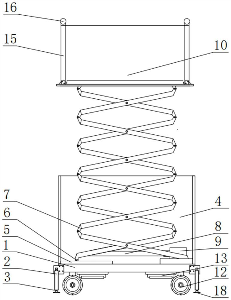
[0025] See Figure 1-2 The present invention provides a technical solution: the hydraulic support rod 2 is provided at the bottom of the base 1, and the hydraulic support rod 2 is fixedly coupled to the support ground foot 3, and the base 1 is fixedly coupled to the case 4. The slide 5 is provided at the bottom of the casing 4, and the slide 5 is embedded, and the pulley 6 is rotated at one end of the folding support arm 7, the folding support arm. 7 The other end is fixed to the bottom of the box body 1, the folding support arm 7 fixed to one end of the telescopic rod 8, and the other end of the telescoping rod 8 fixedly couples the hydraulic pump 9, the hydraulic pressure. The pump 9 is fixedly coupled to the bottom of the casing 1, and the top of the folding support arm 7 is fixedly coupled to the carrier platform 10.

[0026] As a preferred embodiment, the base 1 is provided with the steering wheel 12, and the steering wheel 12 is fixedly coupled to the power device 13.

[002...

Embodiment 2

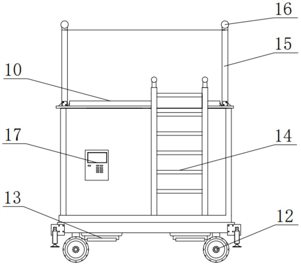
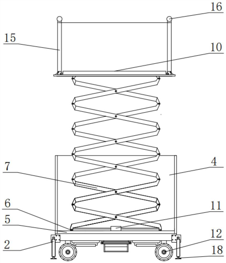
[0034] See Figure 2-3 The present invention provides a technical solution: the hydraulic support rod 2 is provided at the bottom of the base 1, and the hydraulic support rod 2 is fixedly coupled to the support ground foot 3, and the base 1 is fixedly coupled to the case 4. The slide 5 is provided at the bottom of the casing 4, and the slide 5 is embedded, and the pulley 6 is rotatably coupled to both ends of the folded support arm 7, the folding support The bottom of the arm 7 is fixed to both ends of the tensile unit 11, the stretching machine 11 fixed to the bottom of the casing 1, the top of the folding support arm 7 fixed to the carrier platform 10.

[0035] As a preferred embodiment, the base 1 is provided with the steering wheel 12, and the steering wheel 12 is fixedly coupled to the power device 13.

[0036] As a preferred embodiment, the climber 14 is disposed outside the casing 1.

[0037] As a preferred embodiment, the carrier 15 is provided on the guardrail 15, and the ...


PUM


Abstract

The invention discloses a safe bracket for a cabinet device. The bottom of a base is provided with hydraulic supporting rods; the hydraulic supporting rods are fixedly connected with supporting feet;the base is fixedly connected with a box body; the bottom of the box body is provided with a slide way; a pulley is embedded into the slide way; and the pulley is rotationally connected to one end ofa folding supporting arm. The other end of the folding supporting arm is fixedly connected to the bottom of the box body; the bottom of the folding supporting arm is fixedly connected to one end of atelescoping rod; the other end of the telescoping rod is fixedly connected with a hydraulic pump; the hydraulic pump is fixedly connected to the bottom of the box body; and the top of the folding supporting arm is fixedly connected with the bearing platform. The safe bracket fills up the gap that the type of cabinet device with the weight equal to or lower than 200 kg is provided with a safe tool;and the events are avoided that a worker is sprained and bruised due to the overweight of the device when installing the device.

Description

Technical field [0001] The present invention relates to the field of elevator, and is specifically a cabinet equipment safety bracket. Background technique [0002] Traditional cabinet equipment often requires staff to transport cabinet equipment to a height, workflow is rough, and the weight is large, and it is easy to move by manpower, there is a need for an elevator. Secondary cabinet equipment installation, the announcement of the Chinese invention patent for CN100515917 publishes a cutting-type lift, including platform, chassis, cutting arm, cylinder, up and down, connecting rod, hydraulic system; two-cutting arms in the center The rotation is coupled to the cutting sheet; on the two-shear arm of the shears, the lower end is rotated, the chassis is rotated, slide coupling; the upper and lower crossings are coupled to the front and rear shears corresponding to the cutting arm; the cylinder of the cylinder and the lower Turn the coupling; one end of the connecting rod is coupl...

Claims


Application Information

Patent Timeline
IPC IPC(8): B66F11/04B66F17/00
CPCB66F11/042B66F17/006
Inventor 魏东旭李学斌代东旭宁雅卉张鑫浩
Owner BENXI POWER SUPPLY COMPANY OF STATE GRID LIAONINGELECTRIC POWER SUPPLY
Why Eureka
Try Eureka