
Retaining shoulder type vibration reduction fastener

A vibration-damping fastener and shoulder-type technology, which is applied in the field of rail vibration reduction, can solve problems such as difficulty in ensuring accuracy, difficulty in matching the distance-adjusting cover plate and the lower backing plate, and labor-intensive and time-consuming problems, so as to improve the matching effect and improve the gear Tooth fit effect, the effect of improving the lateral limit ability

Inactive Publication Date: 2021-03-16
CHINA RAILWAY ENG CONSULTING GRP CO LTD +1
View PDF9 Cites 0 Cited by
  • Summary
  • Abstract
  • Description
  • Claims
  • Application Information

AI Technical Summary

Problems solved by technology

However, in actual production, the upper backing plate and the lower backing plate are produced by casting process, and its accuracy is difficult to meet the requirements of actual assembly, resulting in the need to repeatedly modify and debug the mold in production to achieve the best fit state, which is labor-intensive and time-consuming
In addition, there is also the problem that the distance-adjustable cover plate is prone to relative deflection with the fastener system during installation, and the cooperation between the distance-adjustable cover plate and the lower backing plate is difficult

Method used


Image

  • Retaining shoulder type vibration reduction fastener
  • Retaining shoulder type vibration reduction fastener
  • Retaining shoulder type vibration reduction fastener

Examples


Embodiment Construction

[0023] The technical solution of the present invention will be described in detail below in conjunction with the accompanying drawings and specific embodiments. It should be understood that these embodiments are only used to illustrate the present invention and are not intended to limit the scope of the present invention. After reading the present invention, those skilled in the art Modifications to various equivalent forms of the present invention fall within the scope defined by the appended claims of the present application.

[0024] It should be noted that when an element is referred to as being “disposed on” another element, it may be directly on the other element or there may also be an intervening element. When an element is referred to as being "connected to" another element, it can be directly connected to the other element or intervening elements may also be present. As used herein, the terms "vertical", "horizontal", "upper", "lower", "left", "right" and similar exp...


PUM


Abstract

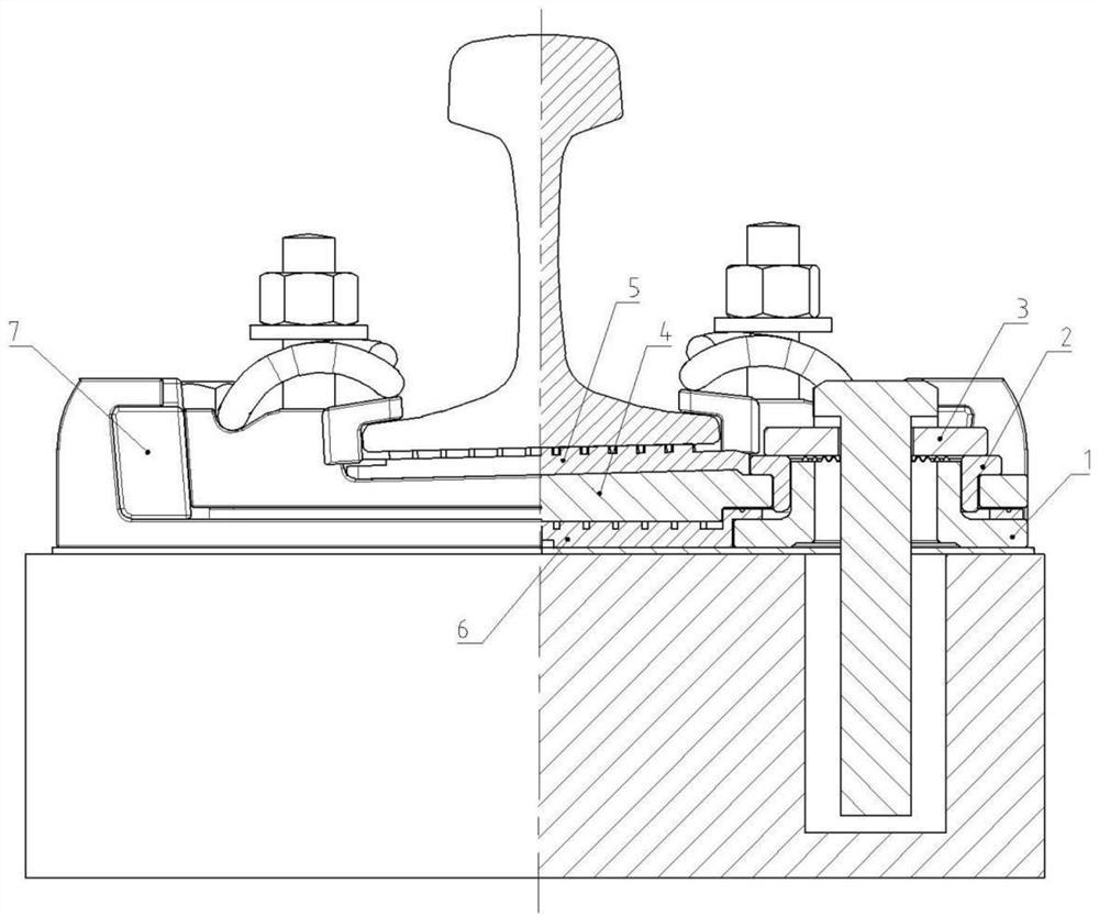
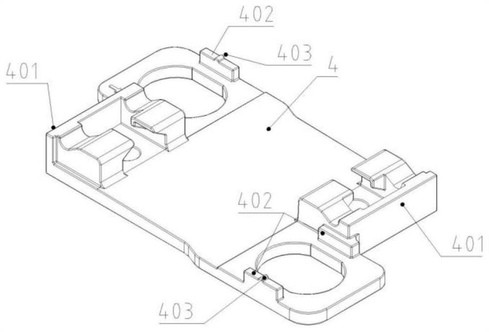
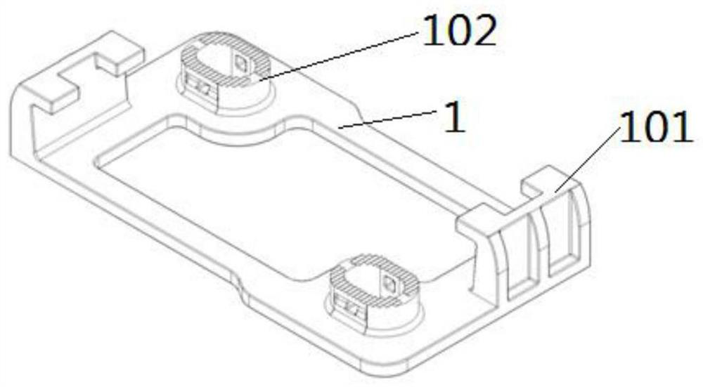
The invention discloses a retaining shoulder type vibration reduction fastener which comprises an upper base plate; a lower base plate; the lower base plate is provided with a first transverse stop shoulder and a second transverse stop shoulder; the upper base plate is provided with a first transverse limiting surface and a second transverse limiting surface; the first transverse stop shoulder andthe first transverse limiting surface are limited through a first transverse stop block, and the second transverse stop shoulder and the second transverse limiting surface are limited through a second transverse stop block; the first transverse stop block is provided with a first matching limiting face making contact with the first transverse limiting face, and the second transverse stop block isprovided with a second matching limiting face making contact with the second transverse limiting face. The first transverse limiting face and the second transverse limiting face are both first wedge-shaped faces, and the first matching limiting face and the second matching limiting face are both second wedge-shaped faces matched with the first wedge-shaped faces. The matching difficulty among theupper base plate, the transverse stop block and the lower base plate is reduced, and the transverse limiting capacity is improved; the tooth matching effect between the distance adjusting cover plateand the lower base plate is improved; and the distance adjusting cover plate is prevented from deflecting during installation.

Description

technical field [0001] This specification relates to the field of rail vibration reduction, in particular to a shoulder type vibration reduction fastener. Background technique [0002] How to solve the impact of vibration and noise on the environment and residents' life in rail transit has become the focus of people's attention on subway construction, and it has also become one of the keys to the sustainable development of urban rail transit construction. Due to the limited vibration reduction effect of traditional vibration reduction technology in terms of vibration reduction and noise reduction, the vibration and noise generated by trains passing by will still directly affect people's life and health, and also cause adverse effects on the surrounding environment to a certain extent. [0003] Some types of vibration-damping fasteners have also been introduced on the market, and have achieved certain vibration-reducing effects. Among them, shoulder-damping fasteners have bee...

Claims


Application Information

Patent Timeline
Patent Type & Authority Applications(China)
IPC IPC(8): E01B19/00E01B9/68
CPCE01B19/003E01B9/685
Inventor 马佳骏瞿连辉冉蕾潘涛孙井林王勇杨松薛玥黄庆白健刘雪锋
Owner CHINA RAILWAY ENG CONSULTING GRP CO LTD
Learn More