Inflatable bridge capable of being erected quickly

An inflatable, bridge technology, applied in the direction of erecting/assembling bridges, bridges, bridge parts, etc., to achieve the effect of reducing distance, reducing single-span span, and reducing thickness

Pending Publication Date: 2021-03-16
NO 63921 UNIT OF PLA
View PDF0 Cites 1 Cited by
  • Summary
  • Abstract
  • Description
  • Claims
  • Application Information

AI Technical Summary

Problems solved by technology

There is no report in the field of bridges, especially in the field of rapid bridge erection for emergencies

Method used


Image

  • Inflatable bridge capable of being erected quickly
  • Inflatable bridge capable of being erected quickly
  • Inflatable bridge capable of being erected quickly

Examples


Embodiment 1

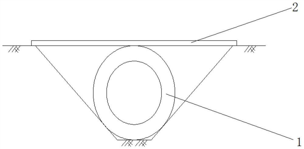
[0035] Embodiment 1, a single inflatable ring unit is used to form the support alone, and the projected circle of the inflatable ring unit is on the same horizontal plane as the span direction of the valley, such as figure 1 , figure 2 As shown, the span of a single span can be reduced to one-half.

Embodiment 2

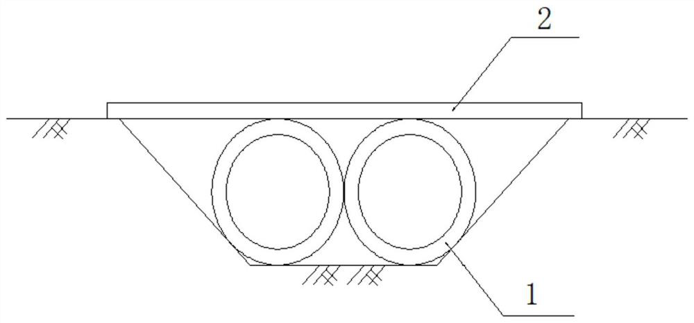
[0036] Embodiment two, using four inflatable ring unit single-layer support, such as image 3 , Figure 4 As shown, the span of a single span can be reduced to one-third. In the span direction of the valley, two inflatable ring units are arranged in line contact to form an inflatable module. The number of inflatable modules is selected according to the depth of the valley. The direction of the valley depth is perpendicular to the span direction of the bridge. Two inflatable modules are used in this example. Two inflatable modules are arranged at intervals perpendicular to the span of the bridge, and can also be in direct contact. Filling rods are filled between the inflatable rings 1, and at the same time, two adjacent inflatable rings 1 are wound with the filling rods by winding tape to form a filling interlocking relationship, and dimples are set between the inflatable rings 1 and the valleys on both sides.

[0037] The inflatable ring unit can also be fixed to the ground...

Embodiment 3

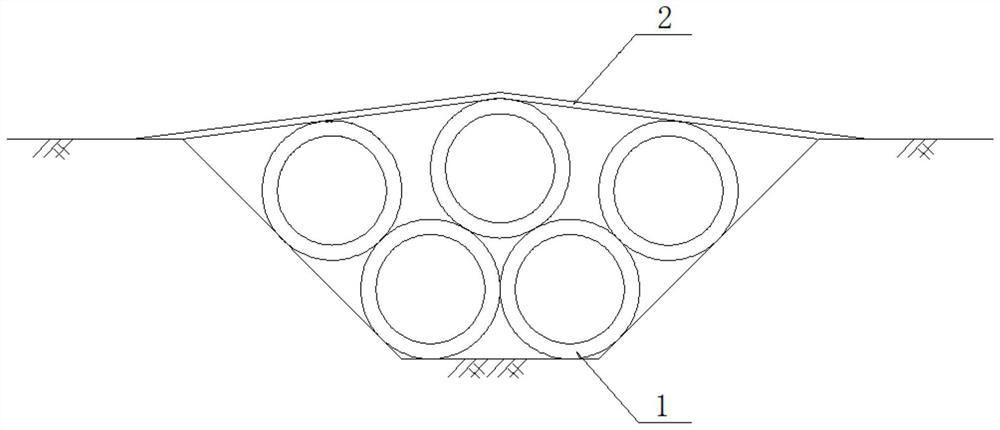
[0038] Embodiment three, using ten inflatable ring units for double-layer support, such as Figure 5 , Figure 6 As shown, the upper inflatable ring unit is in line contact with the two lower inflatable ring units at the same time to form an inflatable module, and the number of inflatable modules is selected according to the depth of the valley. Two inflatable modules are used in this example. Two inflatable modules are arranged at intervals perpendicular to the span of the bridge, and can also be in direct contact. Filling rods are filled between the inflatable rings 1, and at the same time, two adjacent inflatable rings 1 are wound with the filling rods by winding tape to form a filling interlocking relationship, and dimples are set between the inflatable rings 1 and the valleys on both sides.

[0039] The inflatable ring unit can also be fixed to the ground by a fixing device; or the inflatable modules perpendicular to the span direction of the bridge can be fixedly conne...


PUM


Abstract

The invention discloses an inflatable bridge capable of being erected quickly. The inflatable bridge comprises an inflatable ring assembly and a bridge deck bearing plate. The inflation ring assemblyis arranged in a valley to serve as a vertical support. The bridge deck bearing plate is installed on the inflation ring assembly in the valley span direction, and the inflation ring assembly, the inflation ring assembly and valleys on the two sides form a filling interlocking relation. According to the invention, quick assembly and quick erection can be realized.

Description

technical field [0001] The invention relates to the technical field of bridge structures, in particular to a rapidly erected inflatable bridge. Background technique [0002] The inflatable support ring is an inflatable structure with a certain load-bearing capacity. The load-bearing principle of the inflatable structure is: the membrane capsule obtains a large internal pressure after inflating, and the internal pressure causes tension on the membrane surface. The tension of the membrane together with the internal pressure The pressure can resist the external load, so as to realize the function of bearing force. It has the advantages of light weight and strong carrying capacity. At present, inflatable structures are mostly used in the fields of aerospace, near-space vehicles and large buildings. There is no report in the field of bridges, especially in the field of rapid erection of bridges for emergencies. Contents of the invention [0003] In view of this, the present ...

Claims


Application Information

Patent Timeline
Patent Type & Authority Applications(China)
IPC IPC(8): E01D15/12E01D19/00E01D19/12E01D21/00
CPCE01D15/122E01D19/00E01D19/125E01D21/00
Inventor 张立乾闫晶陈红李兵吴星郭宏云孟良孙崇华贾佳王新波田海娇冯中华孔慧
Owner NO 63921 UNIT OF PLA
Why Eureka
Try Eureka