Ice collecting and taking device

An ice mining and ice surface technology, which is used in water conservancy projects, open water surface cleaning, construction, etc., can solve the problem of not being able to clamp ice cubes of any thickness, and achieve an increase in distance, stability, and simple and convenient operation. Effect

Inactive Publication Date: 2021-03-16
哈尔滨市阿城区兴盛腻子粉厂
View PDF1 Cites 0 Cited by
  • Summary
  • Abstract
  • Description
  • Claims
  • Application Information

AI Technical Summary

Problems solved by technology

[0006] 3. The splint in the ice remover of this invention cann

Method used


Image

  • Ice collecting and taking device
  • Ice collecting and taking device
  • Ice collecting and taking device

Examples


specific Embodiment approach 1

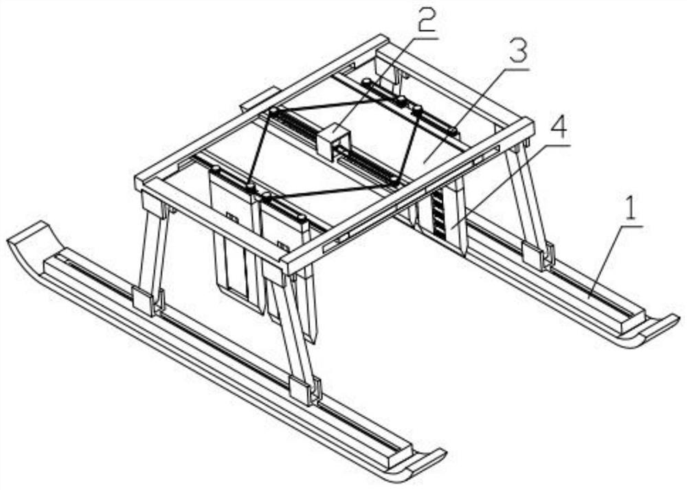
[0040] Combine below Figure 1-15 In this embodiment, an ice harvesting device includes an ice surface lifting mechanism 1, an extension adjustment mechanism 2, a folding plate mechanism 3 and an ice retrieval mechanism 4, and the extension adjustment mechanism 2 is fixedly installed on the ice surface lifting mechanism 1. Above, the folding plate mechanism 3 is installed on the extension adjustment mechanism 2, and the ice taking mechanism 4 is installed on the folding plate mechanism 3.

specific Embodiment approach 2

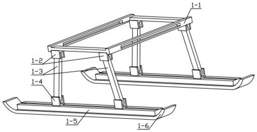
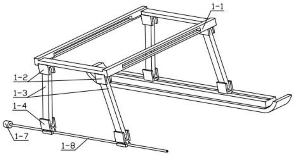
[0042] Combine below Figure 1-15 Describe this embodiment, this embodiment will further explain the first embodiment, the ice surface lifting mechanism 1 includes a square frame 1-1, a hinged head 1-2, a support rod 1-3, a hinged foot 1-4, and a slideway Base plate 1-5, sled plate 1-6, lifting motor 1-7, two-way threaded rod 1-8, are fixedly installed with slideway base plate 1-5 on the sled plate 1-6, the concave of slideway base plate 1-5 The lifting motor 1-7 is fixedly installed in the groove, and the output end of the lifting motor 1-7 is fixedly installed with a two-way threaded rod 1-8, and the other end of the two-way threaded rod 1-8 is rotatably installed on the slideway bottom plate 1-5. In the groove, the two-way threaded rod 1-8 is threadedly connected with the hinge foot 1-4, the hinge foot 1-4 is hinged with the support rod 1-3, and the other end of the support rod 1-3 is hinged with the hinge joint 1-2, The hinged head 1-2 is fixedly mounted on the square fra...

specific Embodiment approach 3

[0044] Combine below Figure 1-15 Describe this embodiment, this embodiment will further explain the second embodiment, the extension adjustment mechanism 2 includes a middle plate 2-1, a balance plate 2-2, a chain 2-3, a driving motor 2-4, and a motor chain Wheel 2-5, chain two 2-6, support spring 2-7, two-way output motor 2-8, one-way threaded rod 2-9, sprocket slider 2-10, double-layer sprocket one 2-11, the middle A balance plate 2-2 is fixedly installed on the plate 2-1, a drive motor 2-4 is fixedly installed on the middle plate 2-1, and a motor sprocket 2-5 is fixedly installed on the output end of the drive motor 2-4, and the motor sprocket 2-5 is meshed with chain two 2-6, and chain two 2-6 is meshed with double-layer sprocket one 2-11, and double-layer sprocket one 2-11 rotates and is installed on the chain wheel slide block 2-10 and is provided with In the groove, the sprocket slider 2-10 is slidably installed in the groove provided on the middle plate 2-1, the doub...


PUM


Abstract

The invention relates to an ice collecting device, in particular to an ice collecting and taking device. The device comprises an ice surface lifting mechanism, an extension adjusting mechanism, a plate folding mechanism, and an ice taking mechanism; the extension adjusting mechanism is fixedly mounted on the ice surface lifting mechanism; the plate folding mechanism is mounted on the extension adjusting mechanism; and the ice taking mechanism is mounted on the plate folding mechanism. According to the ice collecting and taking device, ice can be stably taken down from a river surface, the separation phenomenon cannot occur, and the device can be adjusted according to the size of ice blocks, so that the situation that the ice blocks cannot incline in the taking-out process is guaranteed, and the ice blocks can stably ascend.

Description

technical field [0001] The invention relates to an ice harvesting device, in particular to an ice harvesting device. Background technique [0002] Ice sculpture is a landscape with regional characteristics in winter in the north. Every winter, it is necessary to collect a large number of ice cubes on the frozen river. The inventor found that the existing authorized patent, the patent number is: CN201810898215.8- Plant ice harvesting carts on the river in winter. An ice harvesting device is provided, but in this invention, the structure of the ice harvester has some disadvantages. [0003] Disadvantages of the inventive ice remover: [0004] 1. The ice remover of this invention uses splints to take out the ice by clamping, but the volume of ice required for ice sculpture is relatively large, and it is difficult to take out the larger ice by clamping. [0005] 2. There is a splint on both sides of the two-way hydraulic cylinder of the invention. During operation, the splint...

Claims


Application Information

Patent Timeline
IPC IPC(8): E02B15/02
CPCE02B15/02
Inventor 刘春艳
Owner 哈尔滨市阿城区兴盛腻子粉厂
Why Eureka
Try Eureka