
Device for detecting steel bar position in reinforced concrete construction

A technology for reinforced concrete and steel bar location, which is applied in the direction of measuring devices, mechanical measuring devices, and mechanical devices, etc., which can solve the problems of many restrictive factors in the positioning of steel bars and the inability to measure the thickness of the protective layer of steel bars, etc., so as to achieve convenient operation of steel bar positioning and structural Simple and Portable Effect

Pending Publication Date: 2021-03-16
中铁大桥局第九工程有限公司
View PDF0 Cites 0 Cited by
  • Summary
  • Abstract
  • Description
  • Claims
  • Application Information

AI Technical Summary

Problems solved by technology

[0004] The embodiment of the present application provides a device for detecting the position of steel bars in reinforced concrete construction, so as to solve the problem in the related art that there are many limiting factors in the positioning of steel bars in reinforced concrete construction, and it is impossible to measure the thickness of the protective layer of steel bars

Method used


Image

  • Device for detecting steel bar position in reinforced concrete construction
  • Device for detecting steel bar position in reinforced concrete construction
  • Device for detecting steel bar position in reinforced concrete construction

Examples


Embodiment Construction

[0028] In order to make the purposes, technical solutions and advantages of the embodiments of the present application clearer, the technical solutions in the embodiments of the present application will be clearly and completely described below in conjunction with the drawings in the embodiments of the present application. Obviously, the described embodiments It is a part of the embodiments of this application, but not all of them. Based on the embodiments in the present application, all other embodiments obtained by persons of ordinary skill in the art without making creative efforts belong to the protection scope of the present application.

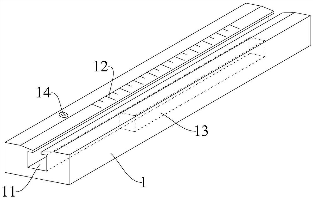
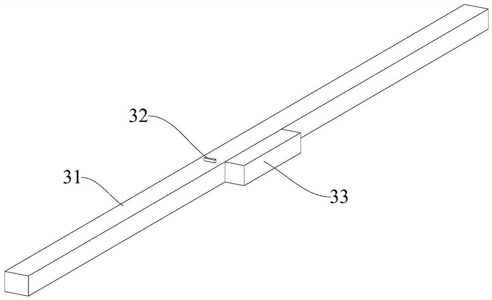
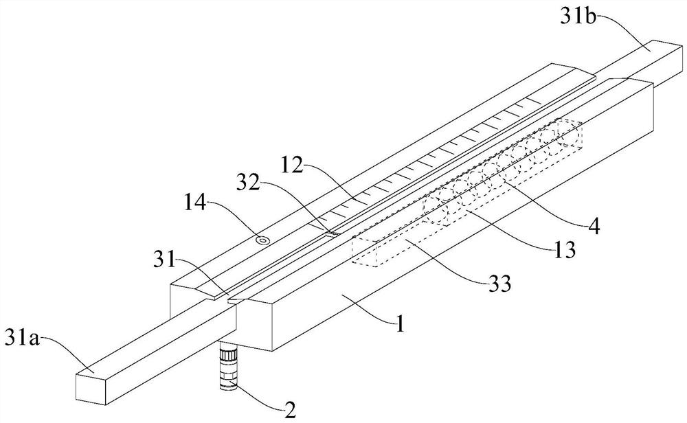
[0029] The embodiment of the present application provides a device for detecting the position of steel bars in reinforced concrete construction. Steel bars are corrected.

[0030] like Figure 1-3 As shown, the embodiment of the present application provides a device for detecting the position of steel bars in reinforced concrete const...


PUM


Abstract

The invention relates to a device for detecting steel bar position in reinforced concrete construction, and relates to the technical field of reinforced concrete engineering construction. The device comprises a caliper base part, a laser sight and a measuring part, wherein the caliper base part is provided with a guide through groove, and the caliper base part is provided with linear scales located at the outer edge of the guide through groove; the laser sight is installed on the lower surface of the caliper base part, and an emitting opening of the laser sight is formed downwards and used foremitting laser; the measuring part comprises a probe rod and an identification piece, wherein the probe rod is adaptively accommodated in the guide through groove and can move along the guide throughgroove, and meanwhile, the front end of the probe rod extends out of the caliper base part and is used for abutting against a to-be-detected steel bar; the identification piece is arranged on the probe rod and is opposite to the linear scales; and the identification piece is used for indicating the moving distance of the probe rod in the guide through groove so as to reflect the position of the to-be-detected steel bar. The device is simple and portable in structure, convenient to position the steel bar and capable of measuring the thicknesses of different steel bar protection layers.

Description

technical field [0001] The application relates to the technical field of reinforced concrete engineering construction, in particular to a device for detecting the position of steel bars in reinforced concrete construction. Background technique [0002] In reinforced concrete structures, the thickness of the steel cover is one of the important indicators to ensure the quality of the structure, and it is of great significance to ensure the safety, applicability and durability of the structure. During the construction of concrete structures, the main reason for the unqualified thickness of the protective layer of steel bars is the displacement of the steel bars, and the position of the steel bars is adjusted when the formwork is installed outside the protective layer of the steel bars. The process is complicated and the construction efficiency is reduced. Therefore, it is necessary to locate the position of the reinforcement before installing the formwork, that is, when the rei...

Claims


Application Information

Patent Timeline
Patent Type & Authority Applications(China)
IPC IPC(8): E04C5/16E04G21/12G01B5/02G01B5/06
CPCE04C5/16E04G21/12E04G21/122E04G21/123G01B5/02G01B5/06
Inventor 汪子鹏周建虹谭春明吴兴富宋岱
Owner 中铁大桥局第九工程有限公司
Learn More