High-precision differential linear displacement sensor

A linear displacement sensor, differential technology, applied in the field of displacement sensor, can solve the problems of missing shell, falling, collision damage, etc., to achieve the effect of easy replacement and maintenance, avoid precision drop, and increase sealing

Inactive Publication Date: 2021-03-16
陕西航宇星测科技有限公司
View PDF3 Cites 2 Cited by
  • Summary
  • Abstract
  • Description
  • Claims
  • Application Information

AI Technical Summary

Problems solved by technology

[0007] The shells of the differential pressure displacement sensors involved in the above three published patents have no protective mechanism. Since the differential pressure displacement sensor is a high-precision and high-precision sensor, during installation, if the differential pressure displacement sensor falls Dropping or colliding with a hard place outside will easily cause the coil in the differential pressure displacement sensor to loosen, and the end of the measuring rod located outside the differential pressure displacement sensor may also be damaged by falling, collision, or even slightly bent. , these will affect the detection accuracy and normal use, therefore, a high-precision differential linear displacement sensor is proposed

Method used


Image

  • High-precision differential linear displacement sensor
  • High-precision differential linear displacement sensor
  • High-precision differential linear displacement sensor

Examples


Embodiment 1

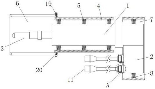
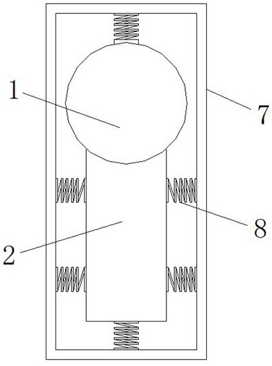
[0025] Example 1 as Figure 1-3 As shown, this high-precision differential linear displacement sensor includes a sensor body 1, the sensor body 1 includes a junction box 2 and a measuring rod 3, the outer side of the sensor body 1 is provided with a main protective sleeve 4, and the main protective sleeve 4 The interior of the sensor is fixed with multiple sets of evenly distributed first springs 5, and the end of the same group of first springs 5 ​​away from the main protective cover 4 is fixedly connected to the side wall of the sensor body 1, and the outer left end of the main protective cover 4 is provided with Secondary protective cover 6, the upper and lower sides of the inner side wall of the secondary protective cover 6 are fixedly connected with slide blocks on the right side, and the upper and lower ends of the outer side wall of the main protective cover 4 are provided with chutes matched with the slide block. 4. There are two locking mechanisms connected to the sec...

Embodiment 2

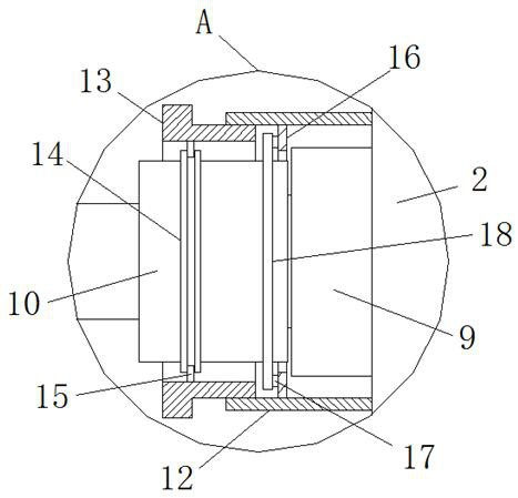
[0026] Embodiment 2 is on the basis of embodiment 1 such as figure 2 As shown, a group of connection sockets 9 are fixedly connected to the left side wall of its junction box 2, and a group of connection sockets 9 are electrically connected with the output end of the sensor body 1, and each connection socket 9 output ends are electrically plugged with a Adapter 10, each adapter 10 is electrically connected with a connector 11 by a wire, each adapter 10 is connected with an anti-off mechanism and is connected with the junction box 2 through an anti-off mechanism, and the adapter 10 is connected to the junction box 9 from the junction socket 9 The separation of the connector 11 from the sensor body 1 can be completed by pulling it out. When the differential linear displacement sensor or the external wire and the connector 11 are damaged, it can be easily replaced and repaired quickly.

Embodiment 3

[0027] Embodiment 3 is such as on the basis of embodiment 2 figure 2 As shown, each of its anti-off mechanisms includes an internal thread sleeve 12, a T-shaped threaded sleeve 13 and a fixed ring 14. The internal thread sleeve 12 is located on the outside of the wiring socket 9, and the right end of the internal thread sleeve 12 is connected to the junction box. 2 is fixedly connected to the left side wall, the inner side wall of the fixed ring 14 is fixedly connected to the left end of the side wall of the same side adapter 10, and the left end of the inner side wall of the T-shaped threaded sleeve 13 is fixedly connected with slide bars 15 on both sides, and the fixed ring The outer ring wall of 14 is provided with the annular chute that matches with slide bar 15, and the right end of T-shaped threaded sleeve 13 outer wall is threadedly connected with the left end of the inner side wall of internal threaded sleeve 12, and twists T-shaped threaded sleeve 13 and makes it with...


PUM


Abstract

The invention relates to the technical field of displacement sensors, and discloses a high-precision differential linear displacement sensor, which comprises a sensor body, the sensor body comprises ajunction box and a measuring rod, the outer side of the sensor body is sleeved with a main protective sleeve, and a plurality of groups of uniformly distributed first springs are fixedly arranged inthe main protective sleeve, the ends, away from the main protective sleeve, of the same set of first springs are fixedly connected with the side wall of the sensor body, the left end of the main protective sleeve is sleeved with an auxiliary protective sleeve, and sliding blocks are fixedly connected to the right sides of the upper and lower ends of the inner side wall of the auxiliary protectivesleeve. The differential linear displacement sensor can be subjected to anti-collision protection, precision reduction or damage of the differential linear displacement sensor due to falling and collision is avoided, meanwhile, the wiring end of the differential linear displacement sensor can be conveniently separated from an external wire, and the maintenance and replacement efficiency is high.

Description

technical field [0001] The invention relates to the technical field of displacement sensors, in particular to a high-precision differential linear displacement sensor. Background technique [0002] The iron core and the coil of the differential linear displacement sensor are not in contact, so there is no wear and tear, and it has the characteristics of super long life. The coil can respond to the small movement of the iron core and generate output, so it has infinite resolution and can measure The range can reach ±0.5mm, high precision, good repeatability, durable. [0003] After retrieval, the Chinese patent publication number is CN202109877U, which discloses a differential pressure-transformation displacement sensor, including a measuring rod, a probe shell, a probe line, a signal amplifier and a power supply output terminal, which are connected sequentially from left to right. A primary coil is provided on one side, and two secondary coils are provided on the other side...

Claims


Application Information

Patent Timeline
Patent Type & Authority Applications(China)
IPC IPC(8): G01B7/02H01R13/639H01R13/52H01R31/06
CPCG01B7/02H01R13/5219H01R13/639H01R31/06
Inventor 张拴祥胡亚兵
Owner 陕西航宇星测科技有限公司
Why Eureka
Try Eureka